Primer paso para empezar a controlar otros componentes desde
el móvil.
Lo más difícil ha sido programar para conectar con el BLE
(No es tan fácil como con Bluetooth clásico y requiere importar una extensión).
Dejo los archivos para que construyáis a partir de este proyecto otros más
complejos (control de otros leds, servos, etc). Importante importar la
extensión .aix en el proyecto de App Inventor 2.
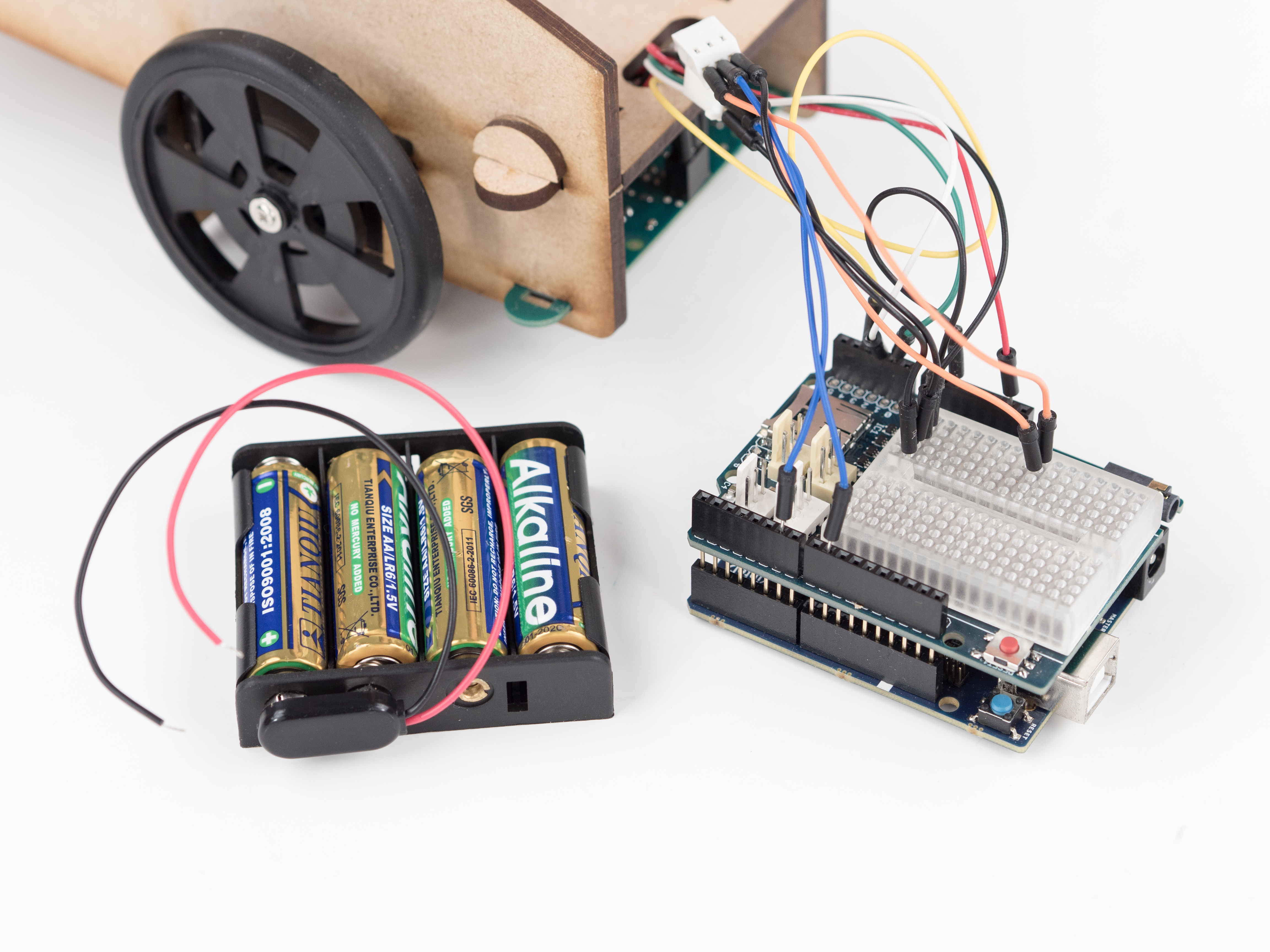
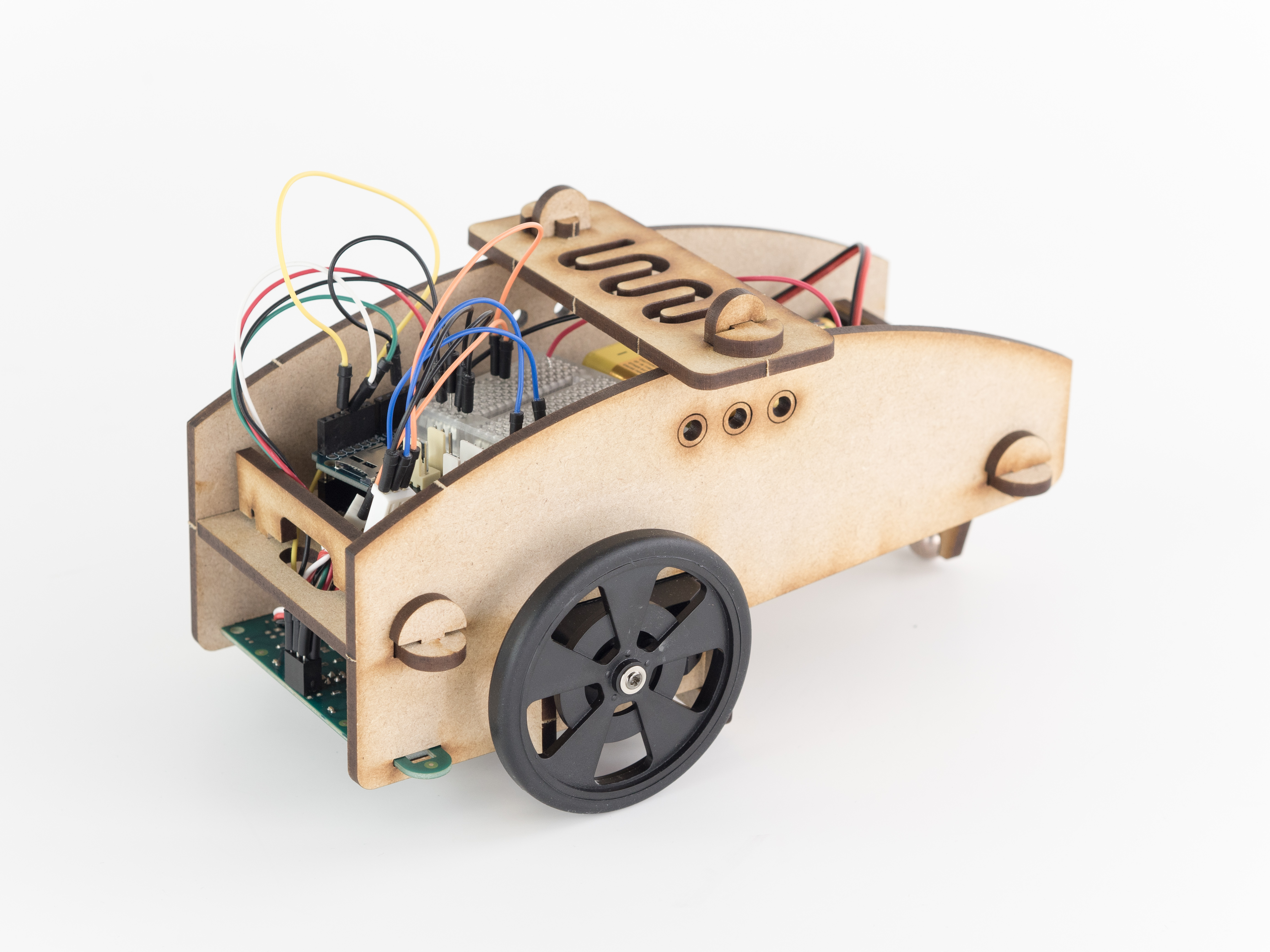
Hola chic@s: Os presento al bicho que vosotros/as habéis diseñado. Os dejo un vídeo y algunos fotos de los detalles. Analizaremos su funcionamiento en clase.
Antes de empezar con el proyecto del Siguelíneas tenemos que instalar Arduino en nuestro ordenador (SO Ubuntu) y la placa Genunino 101 que es la que utilizaremos en el proyecto
Seguir las siguientes instrucciones paso a paso:
4. Abrir la descarga y hacer doble click en el archivo comprimido arduino-1.8.9-linux64.tar.xz
5. Abrir la carpeta descomprimida
6. Copiar la carpeta arduino-1.8.9 y pegarla en la carpeta Personal
7. Abrir el terminal y teclear cd arduino-1.8.9 y pulsar INTRO
8. Teclear ./install.sh y pulsar INTRO
9. En el Escritorio hacer doble click en el archivo Arduino Desktop
10. Click en Confiar y ejecutar
11. Abrir el IDE
12 Herramientas/Placa/Gestor de tarjetas
13. Escribir Intel Curie
14. Seleccionar Intel Curie Boards e instalar la última versión
15. Esperar hasta que termine de instalarse
16. En el terminal teclear cd .. y pulsar INTRO
17. Copiar y pegar en el terminal lo siguiente y pulsar INTRO: chmod +x ~/.arduino15/packages/Intel/hardware/arc32/2.0.4/scripts/create_dfu_udev_rule 18. Copiar y pegar en el terminal lo siguiente y pulsar INTRO: sudo ~/.arduino15/packages/Intel/hardware/arc32/2.0.4/scripts/create_dfu_udev_rule Pedirá la contraseña. Poner usuario y dar a INTRO 19. Abrir el IDE 20. Ir a Programa/Incluir Librería/Administrar Bilbiotecas 21. Escribir Education
22. Instalar Education Shield
23. Cerrar el IDE y volver a abrirlo
24. Conectar la placa
25. Seleccionar placa Arduino Genuino 101
26. Abrir Ejemplo Basics/Blink
27 Cambiar LED BUILTIN por 13 en las tres líneas de código y en delay cambiar 1000 por 300, 2000, etc
28. Subir el programa y comprobar
The Line Follower does exactly what the name suggests, it follows a line. Make it go where ever you want by showing the way with a 3 cm wide, black line.
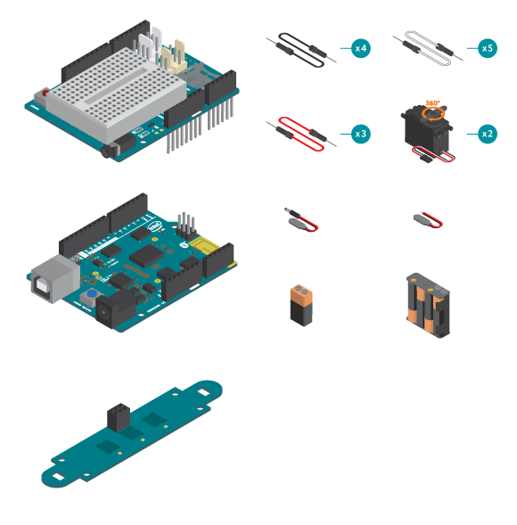
Materials
1 x control board
1 x Education Shield
1 x IR Array
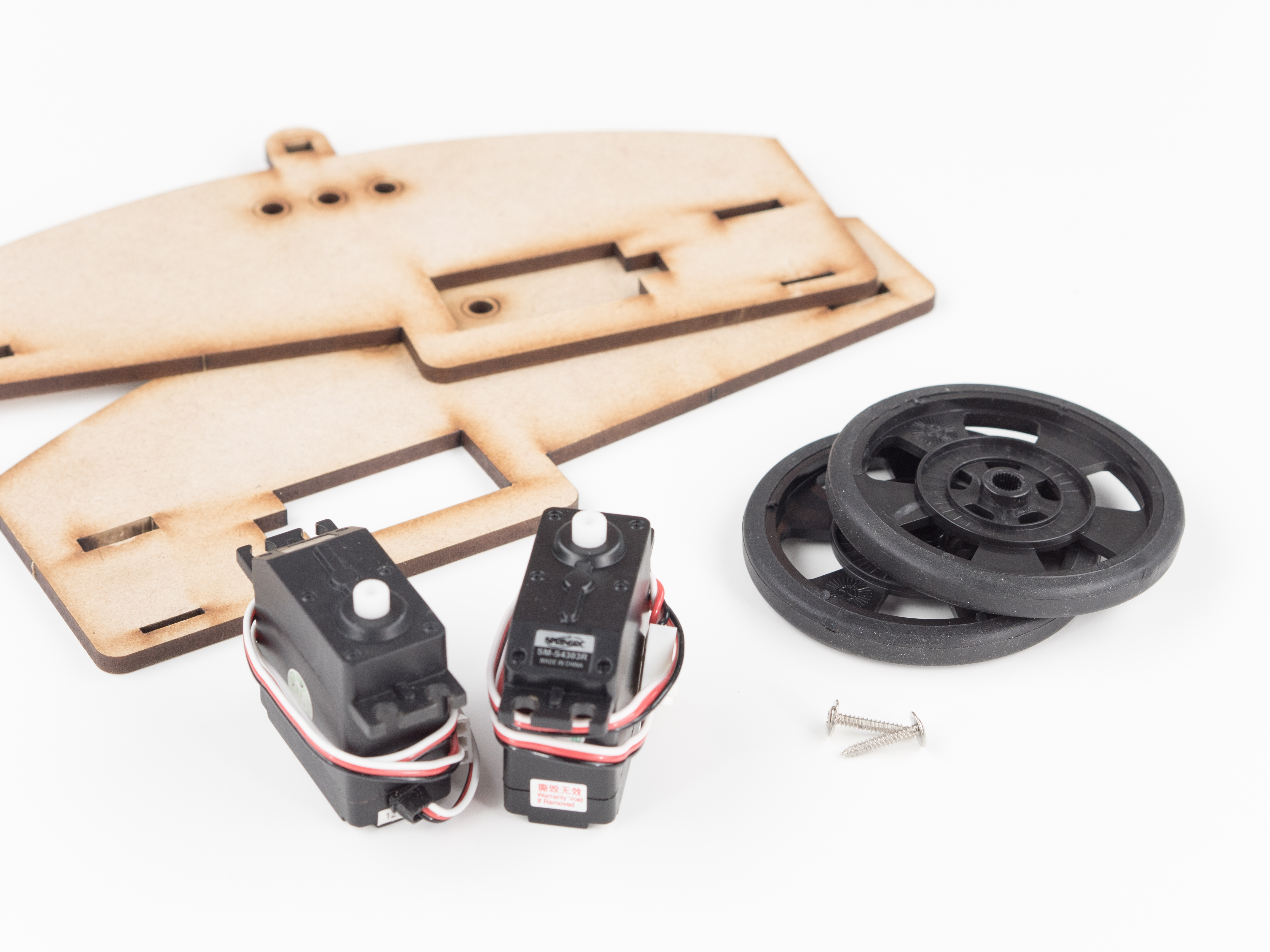
2 x continuous rotation servo
12 x jumper wire
1 x 9V battery
4 x AA battery
1 x AA battery holder
2 x power plug (One without the plug that has two loose wires)
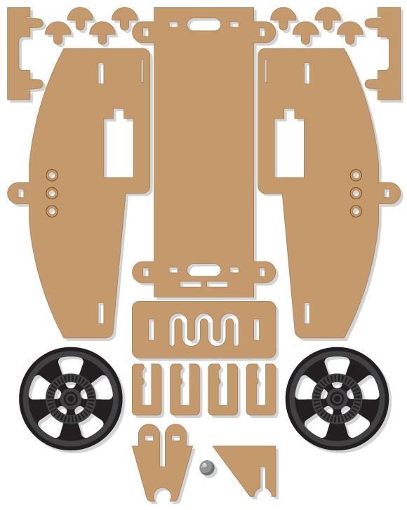
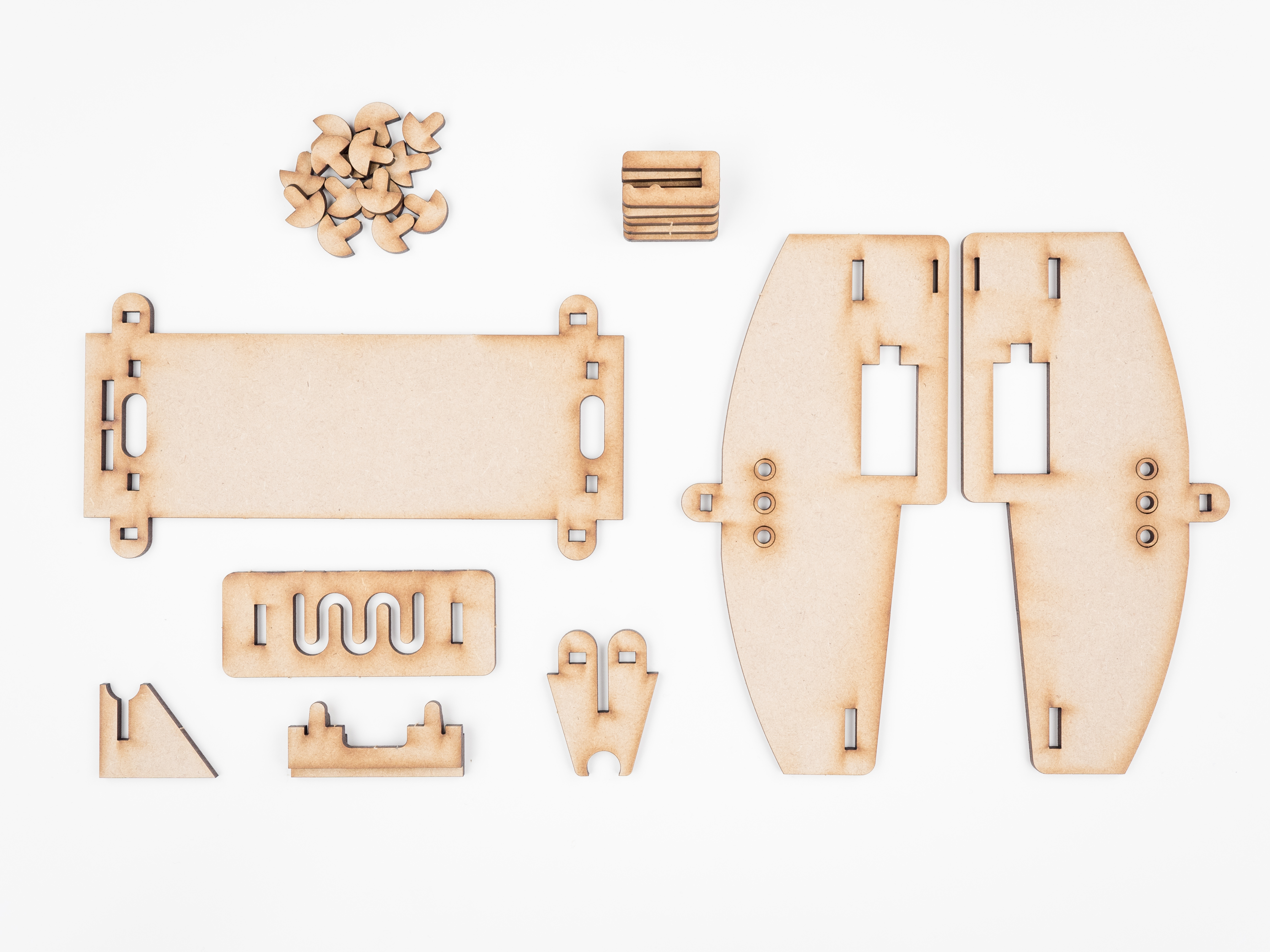
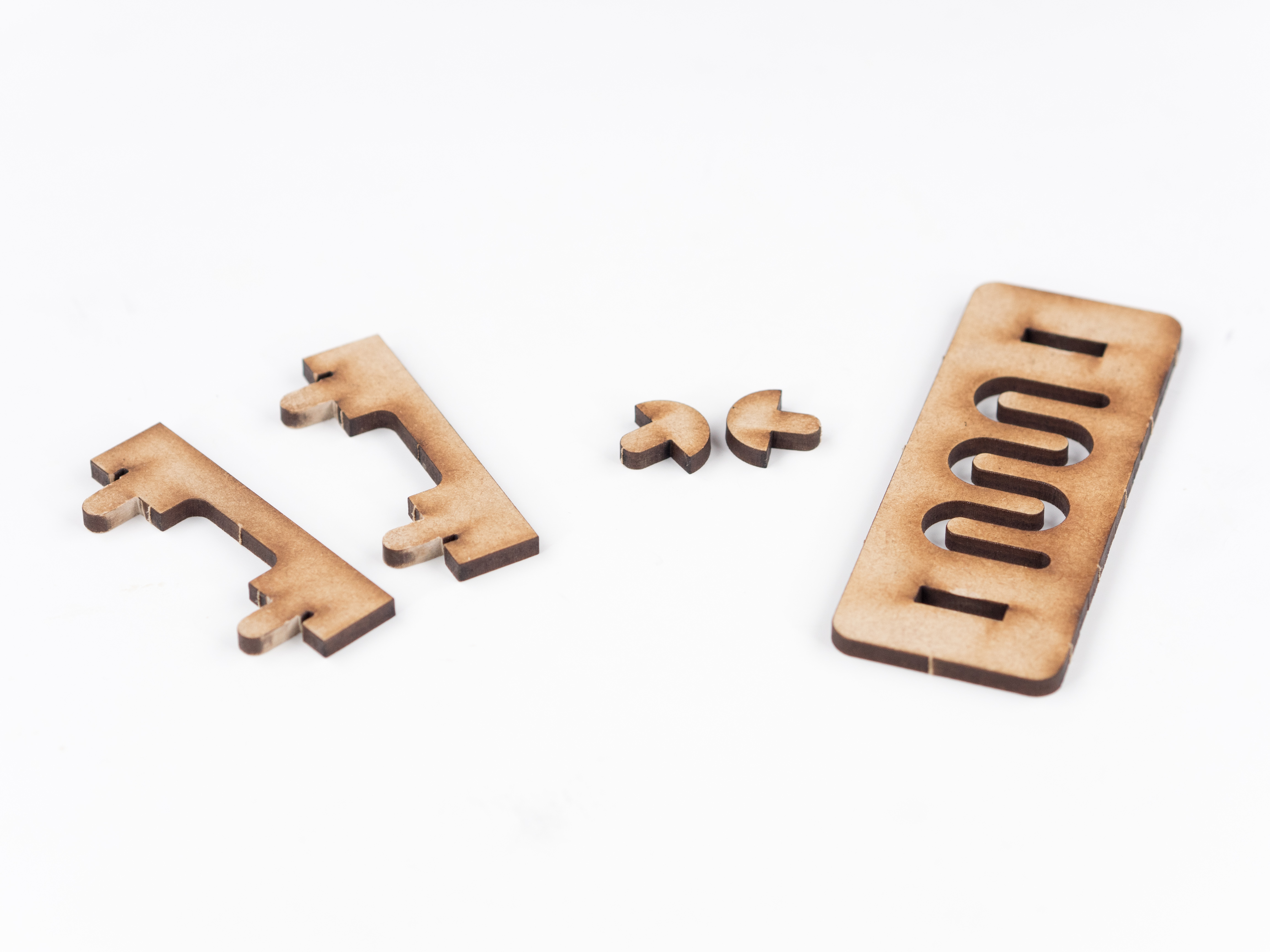
1 x Line follower kit
1 x metal ball
2 x wheel
Other materials:
1 x black tape
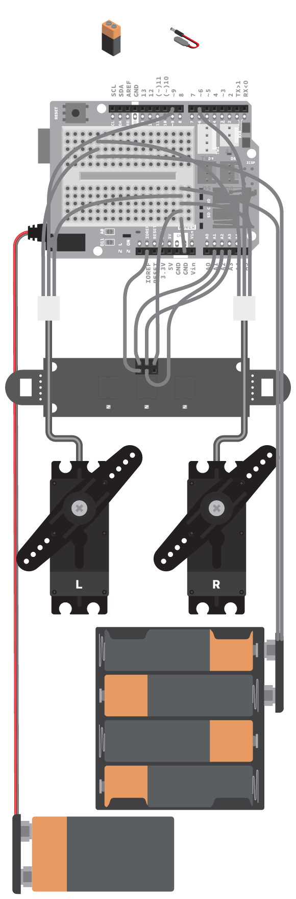
This experiment can be created without the Education shield. You can download the schematics here, and the Fritzing original files can be found in this Github repository.
Instructions
Step 1
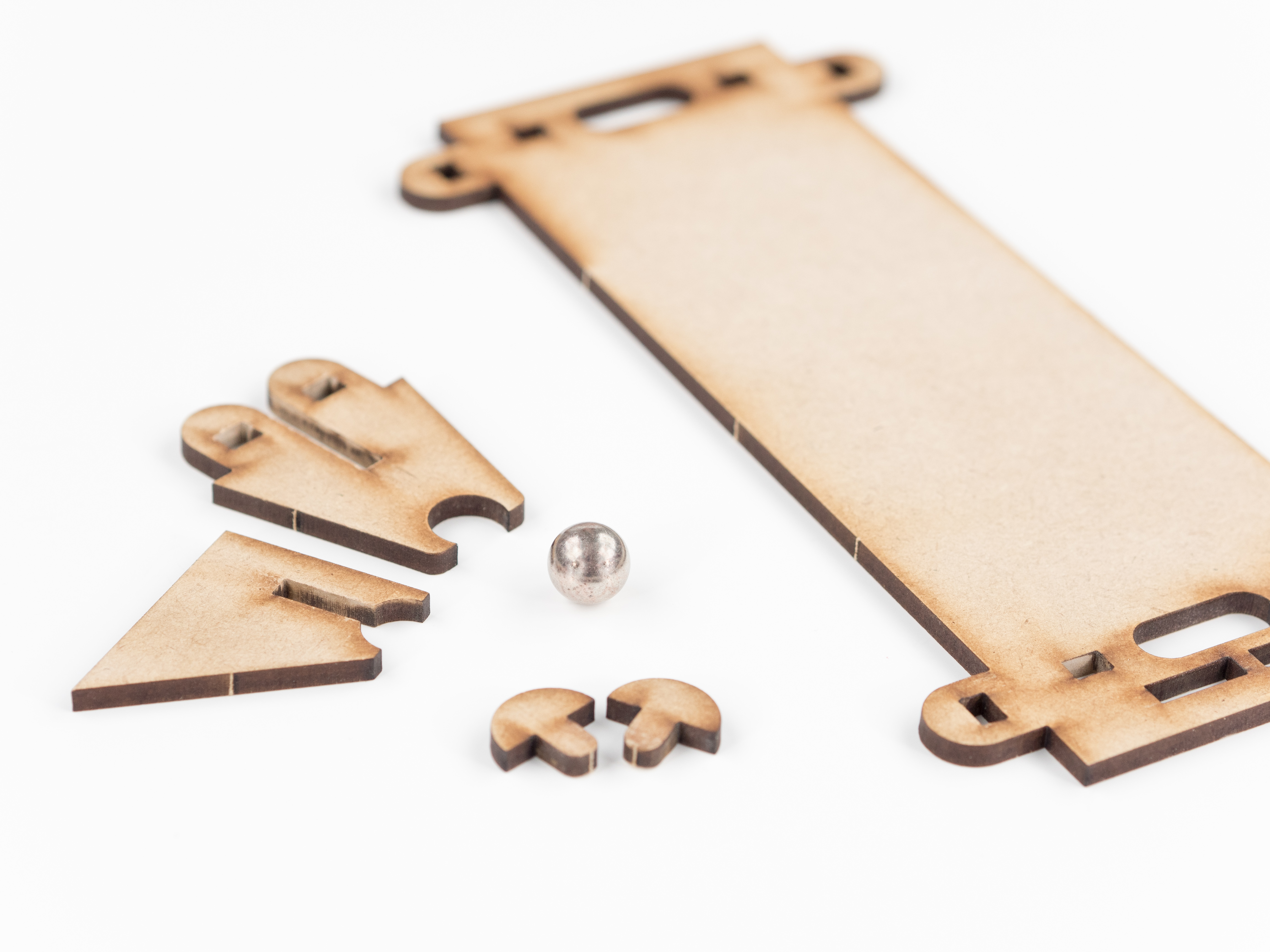
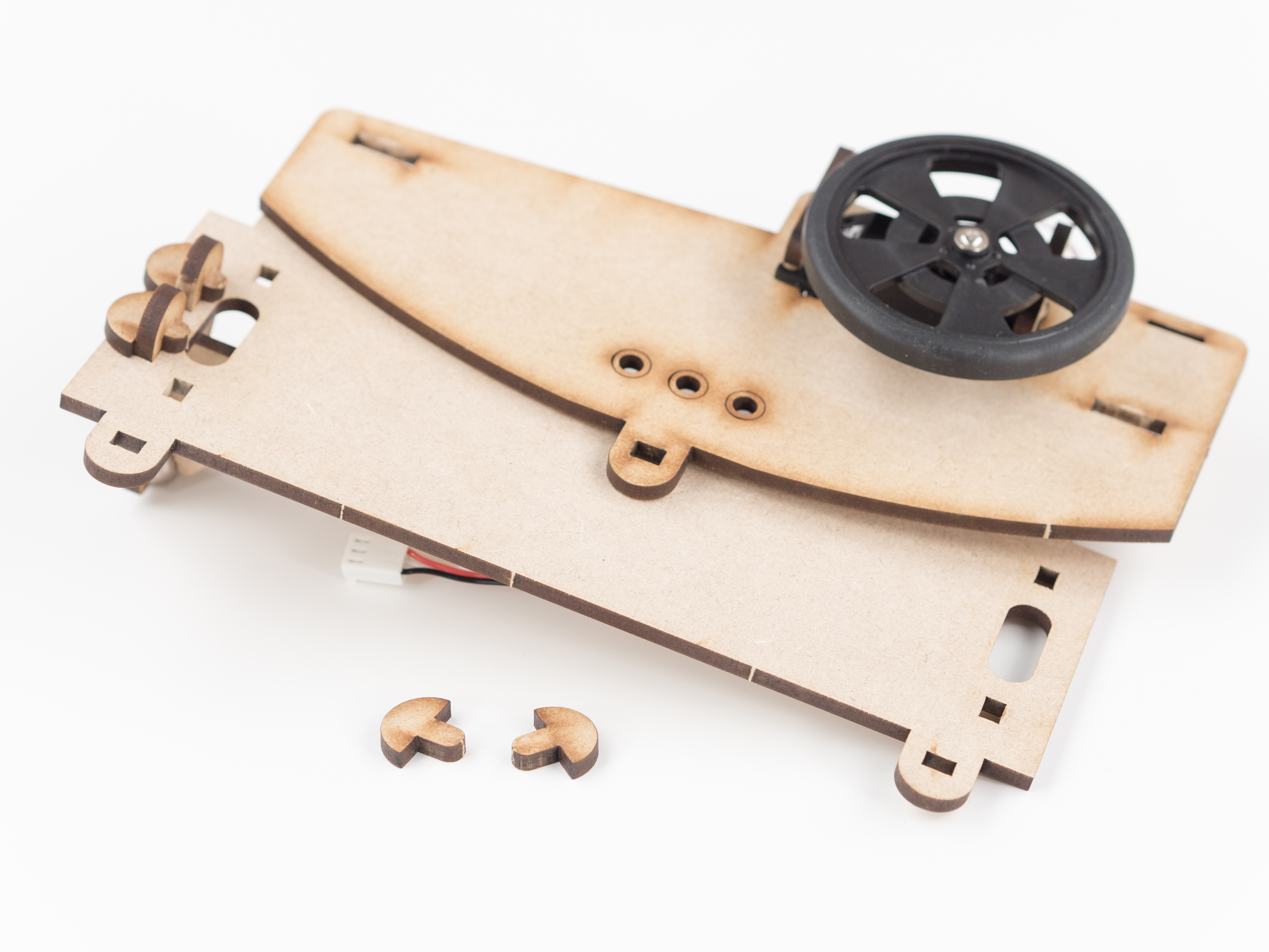
Gather all the construction materials for the Line follower.
Step 2
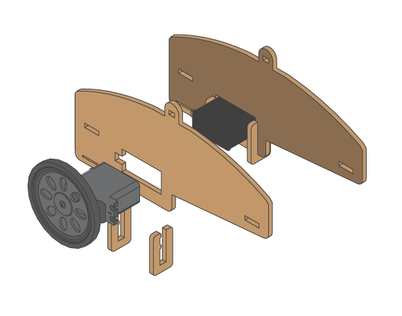
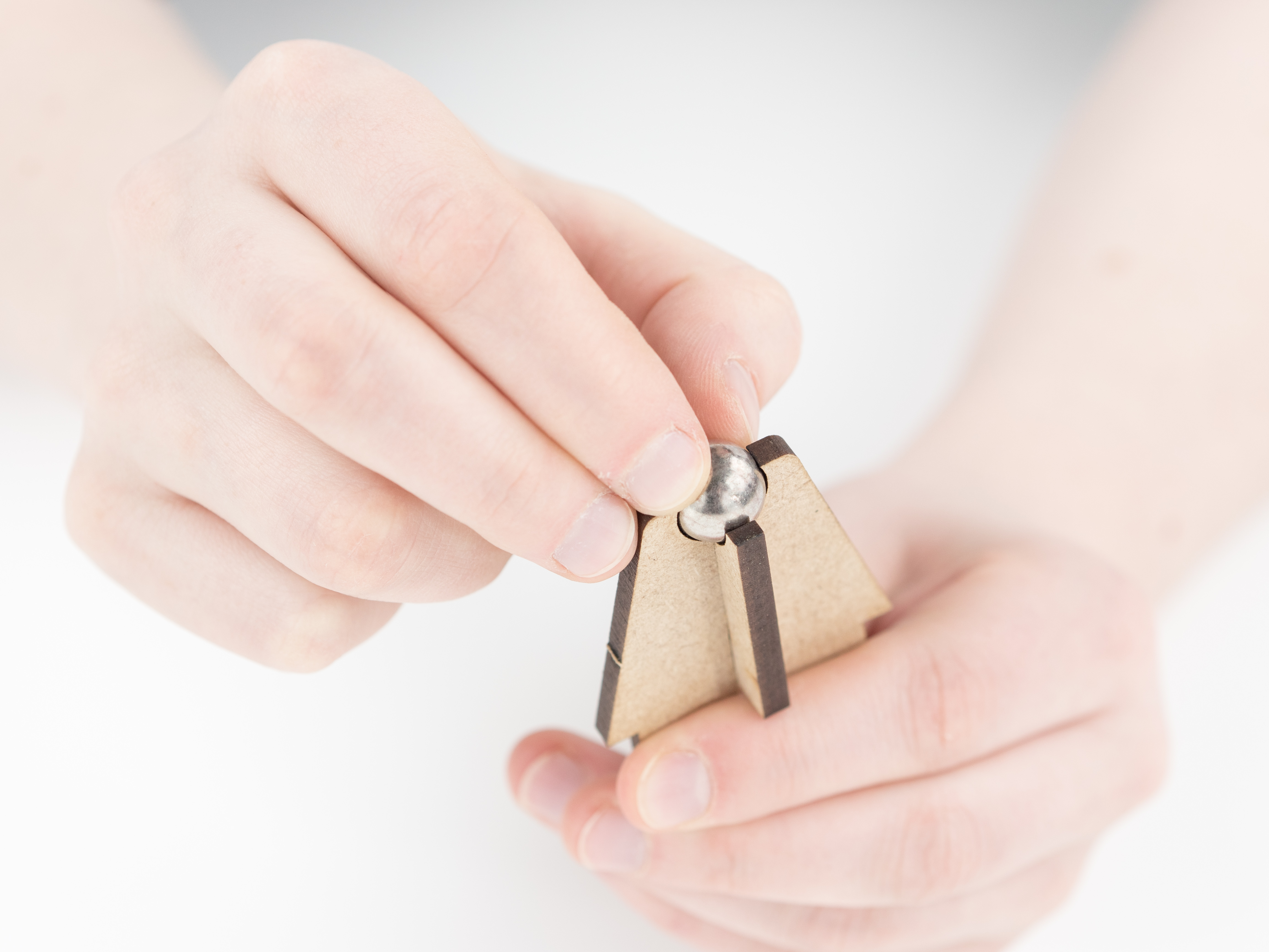
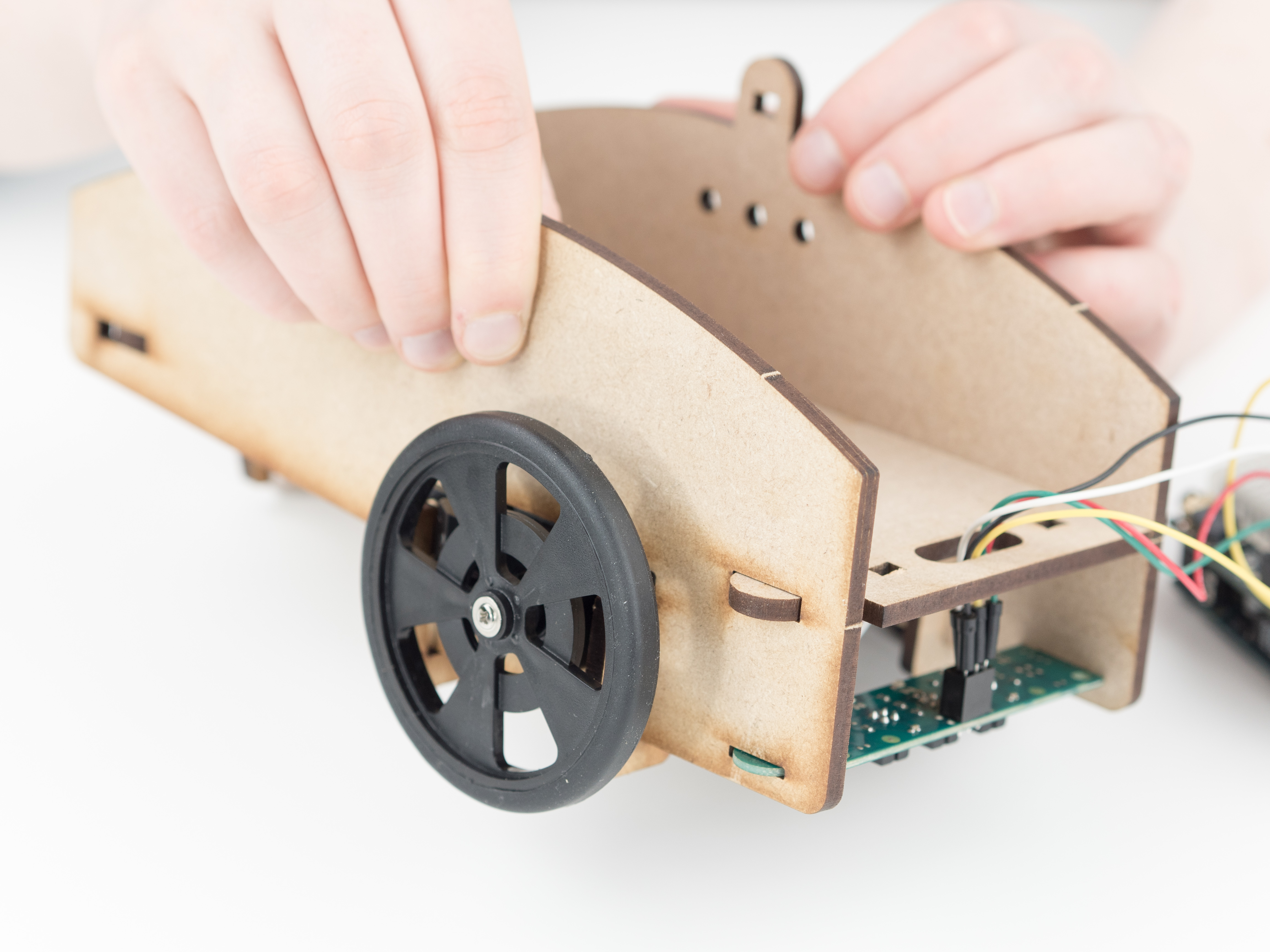
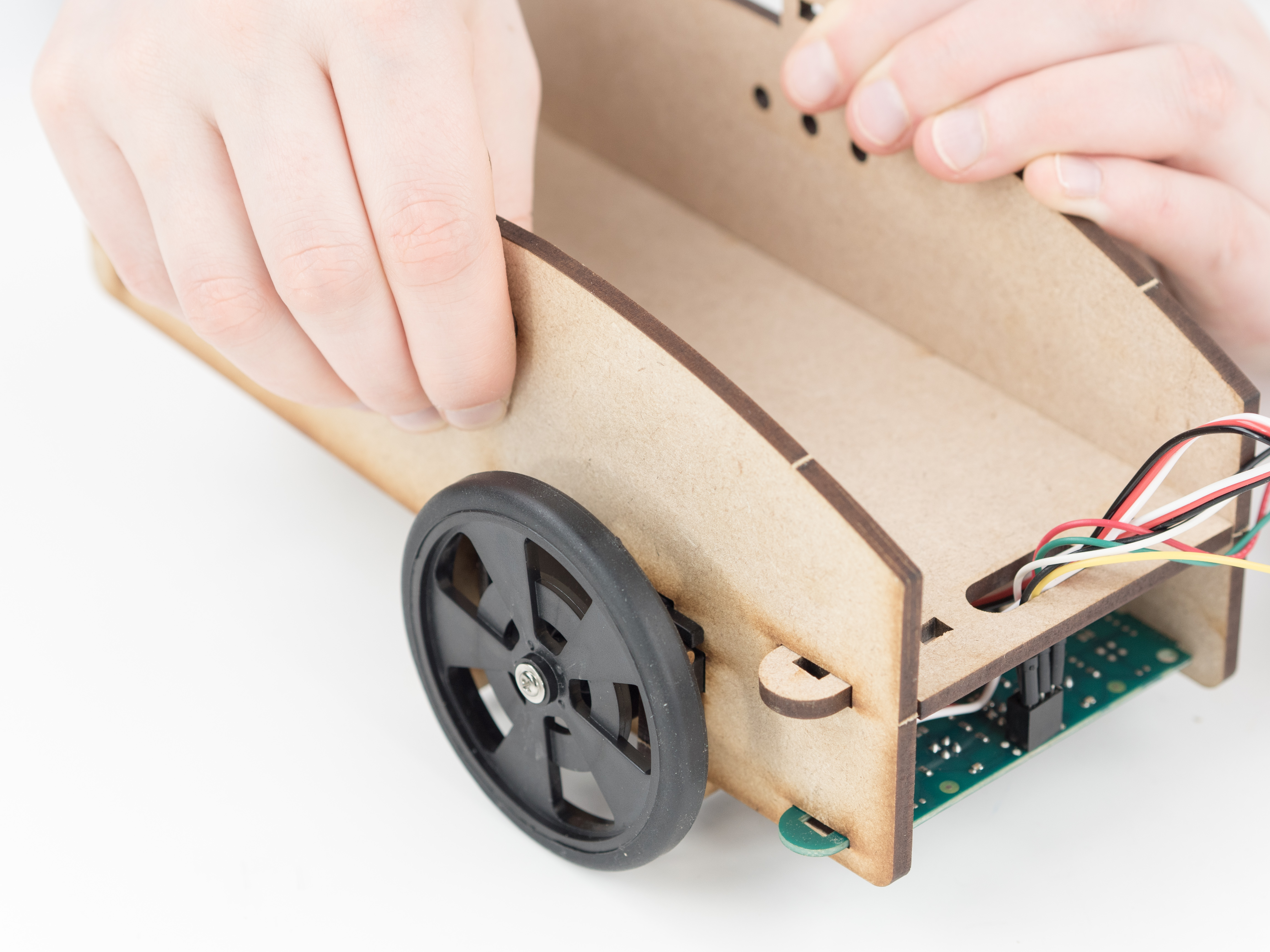
Let's start building the Line follower! If you want some building tips, go to the Building Advices reference.
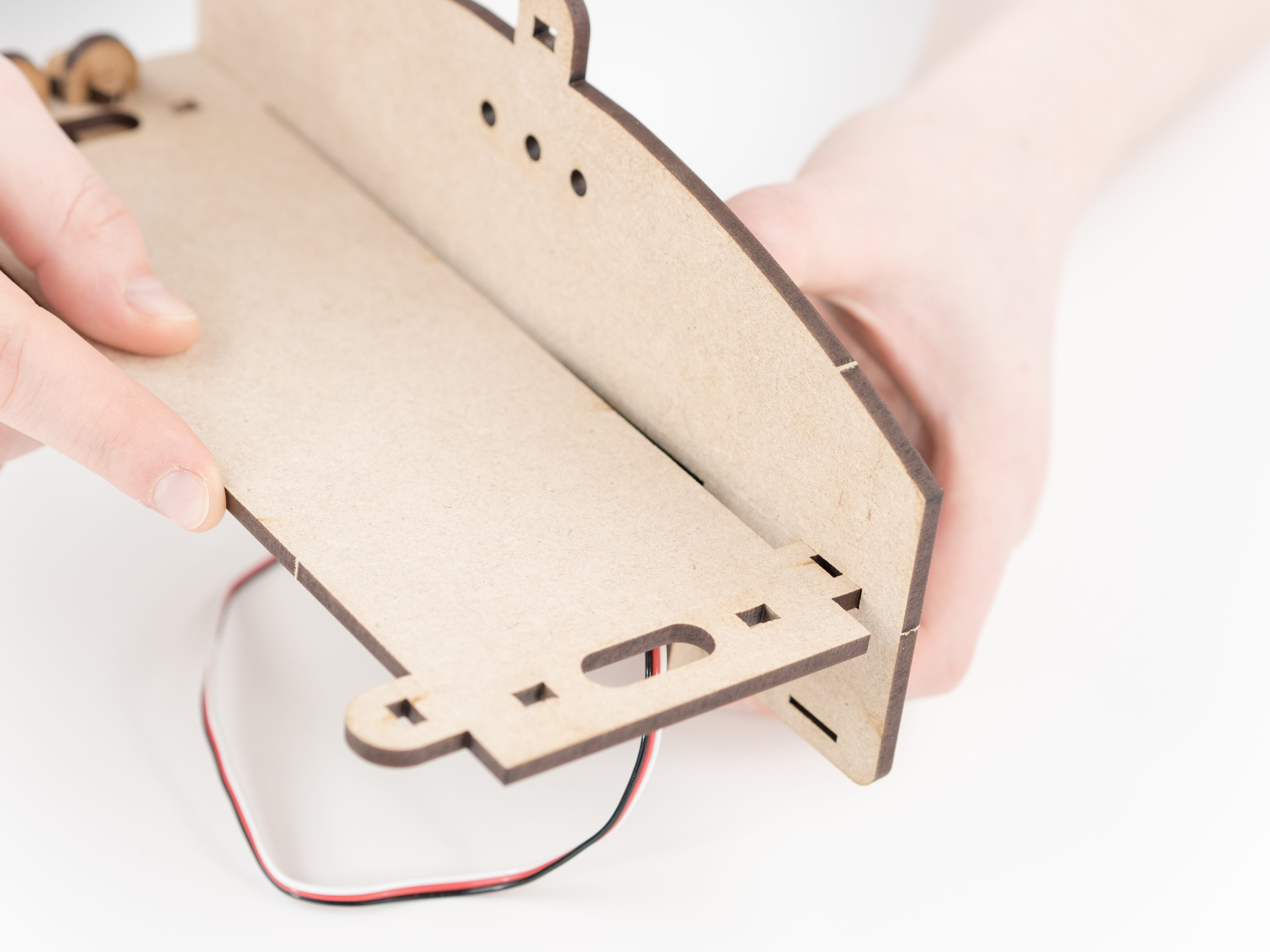
Step 3
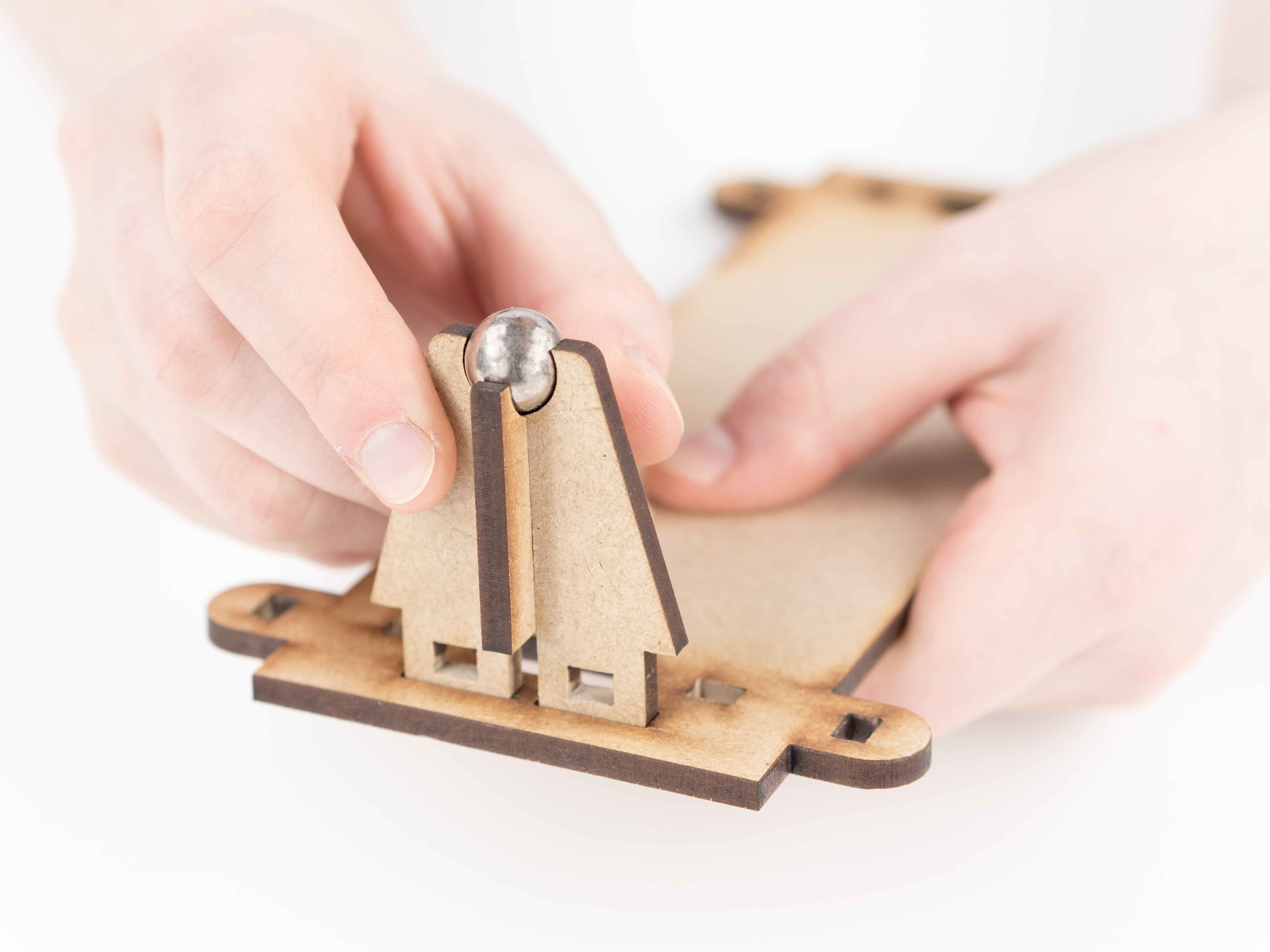
Step 4
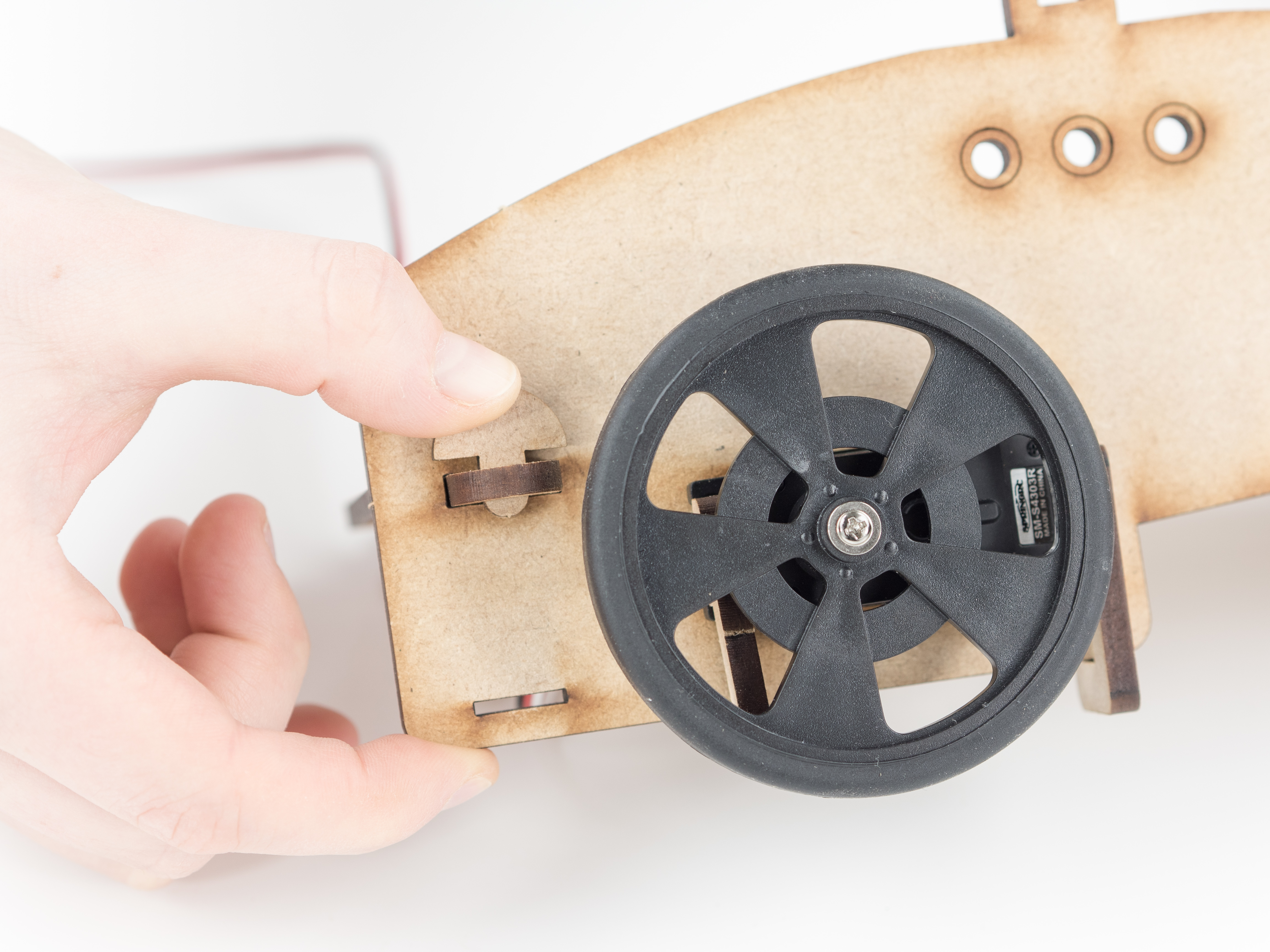
Step 5
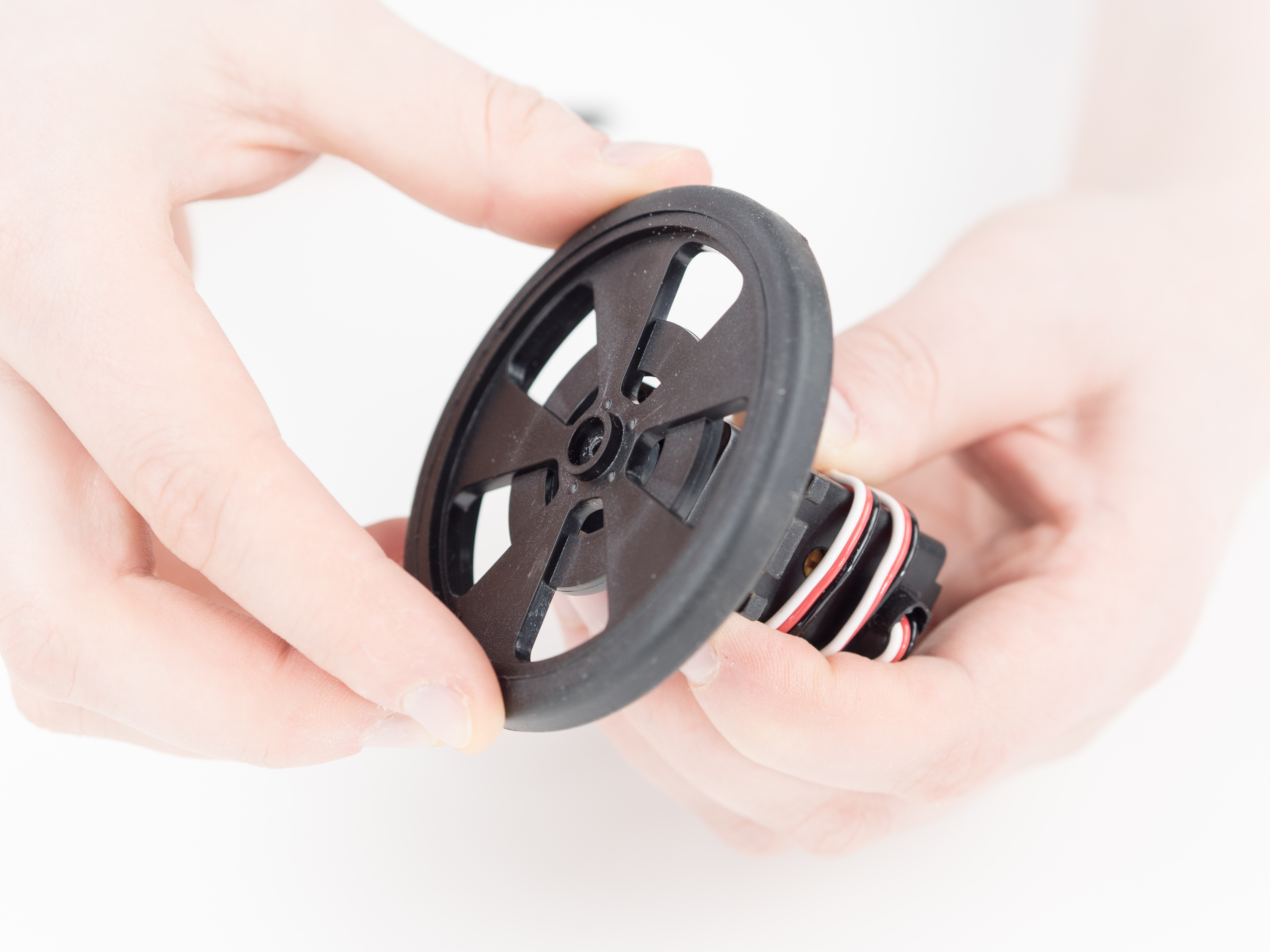
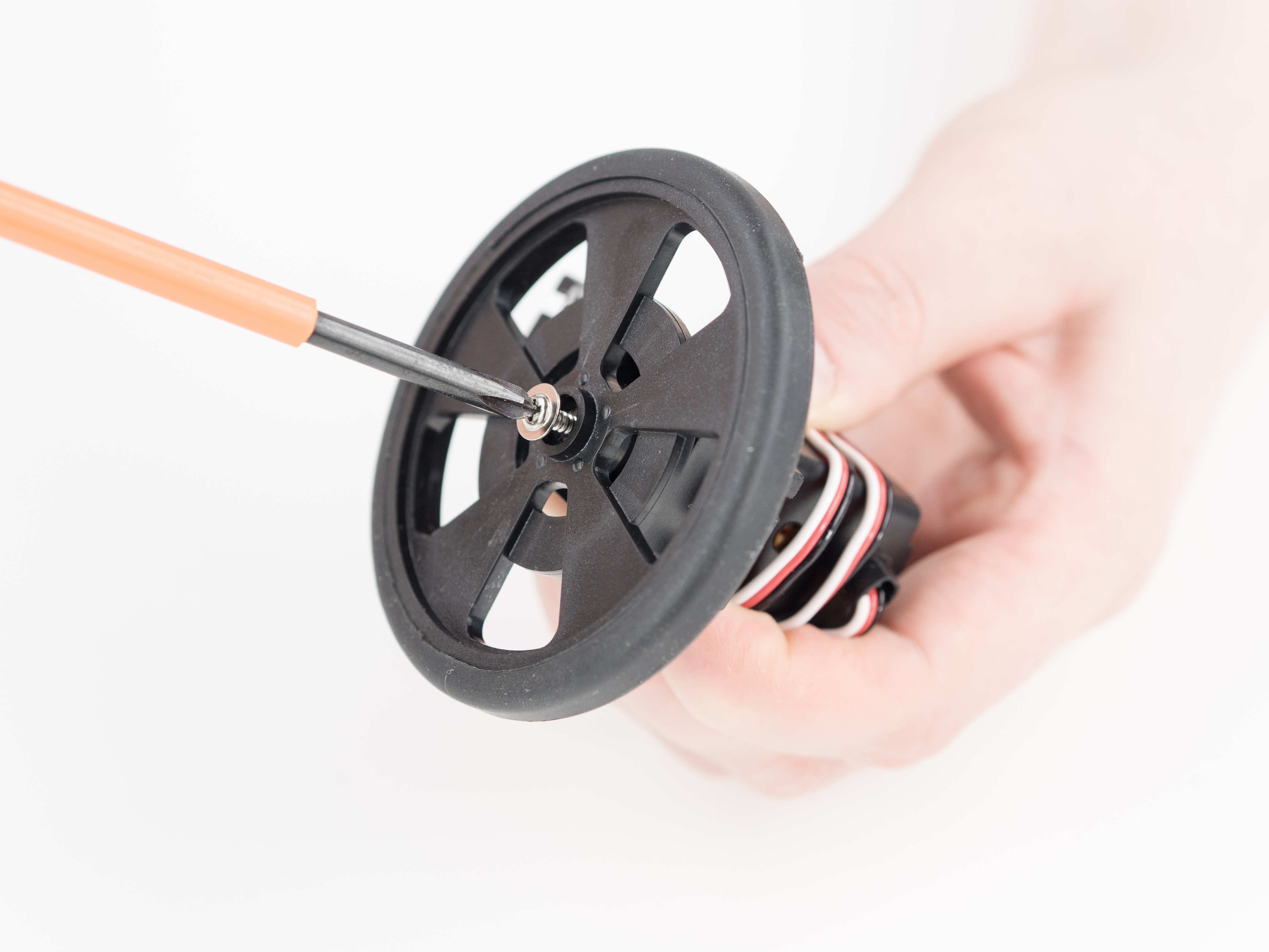
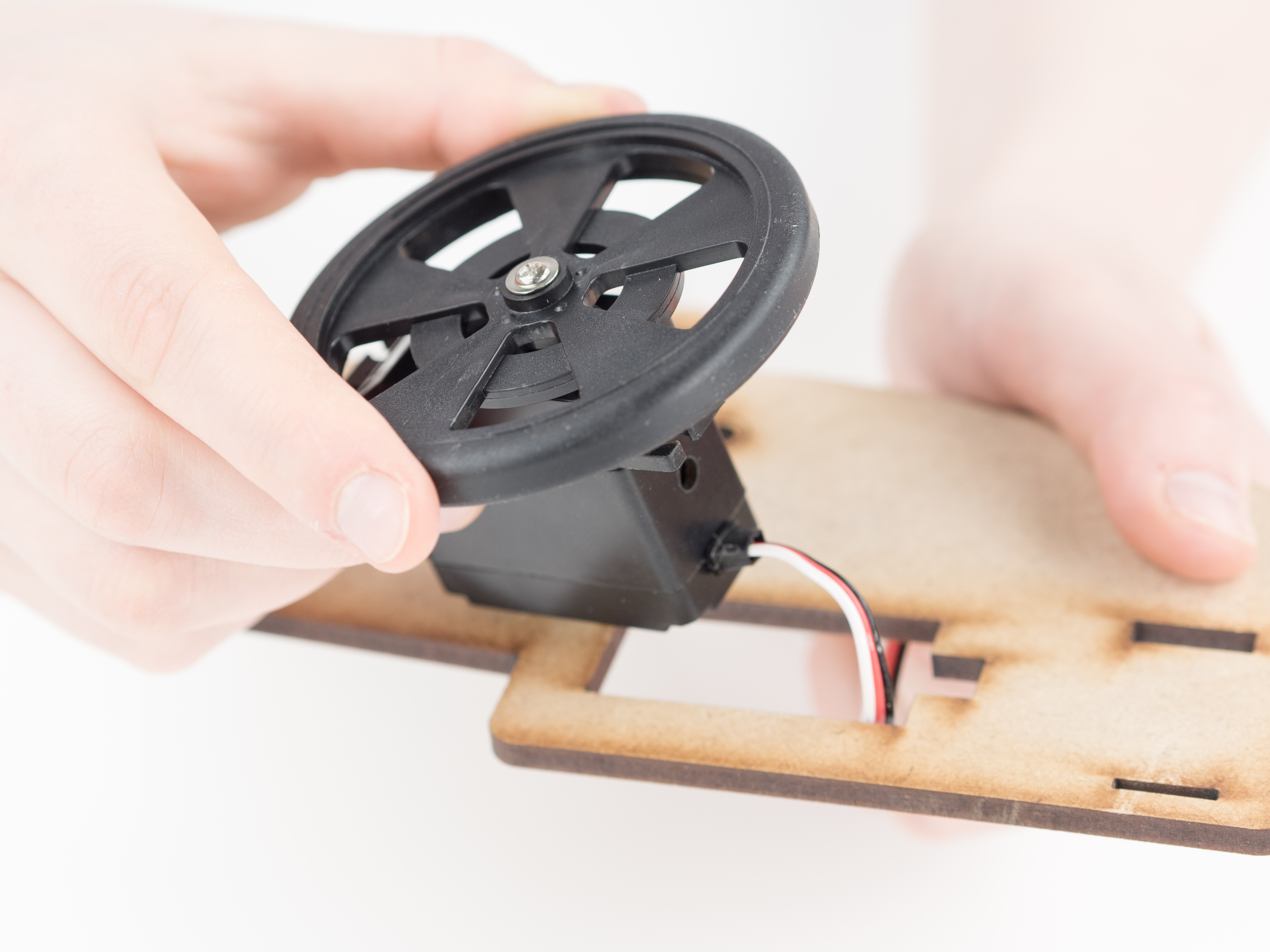
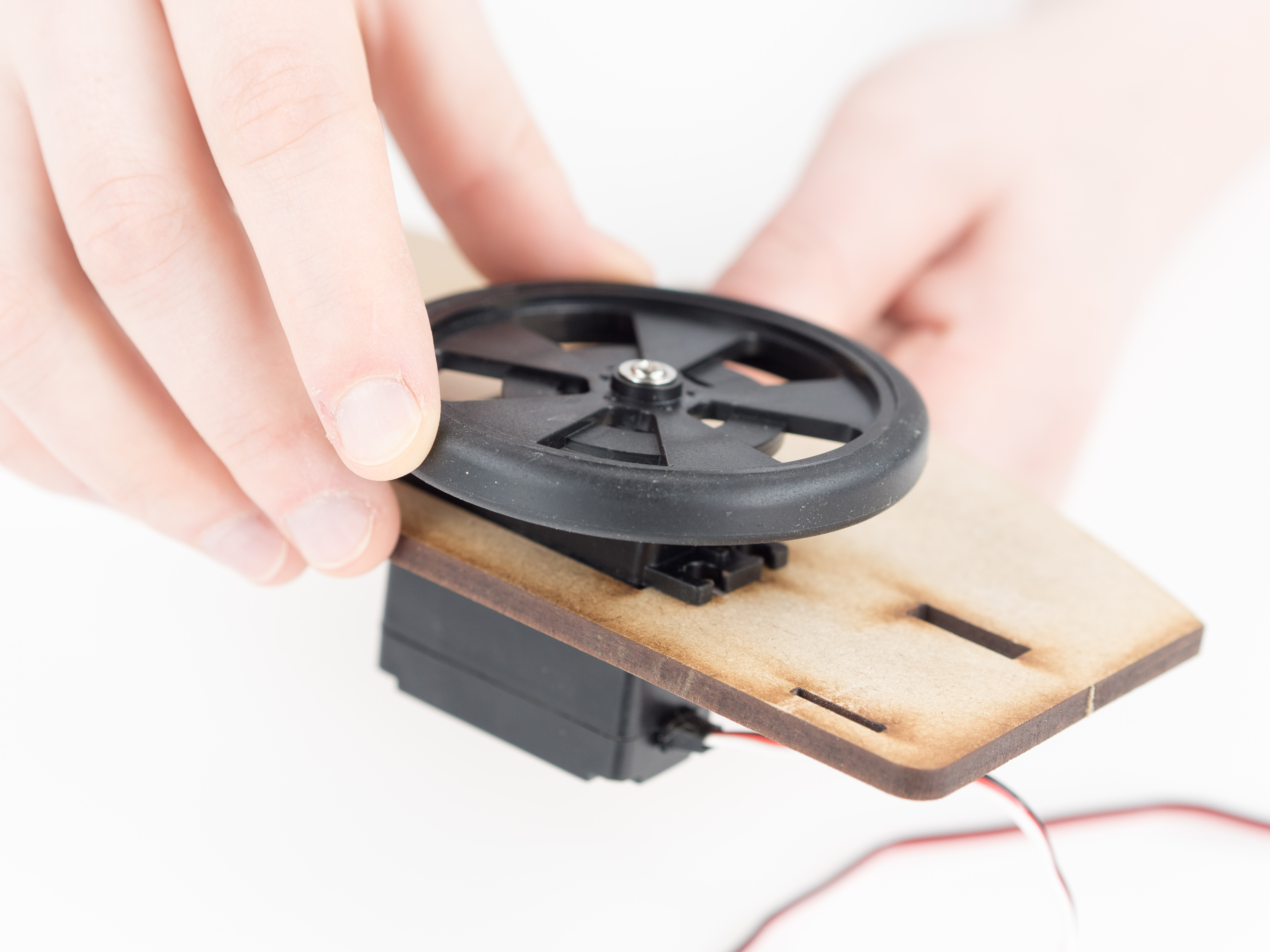
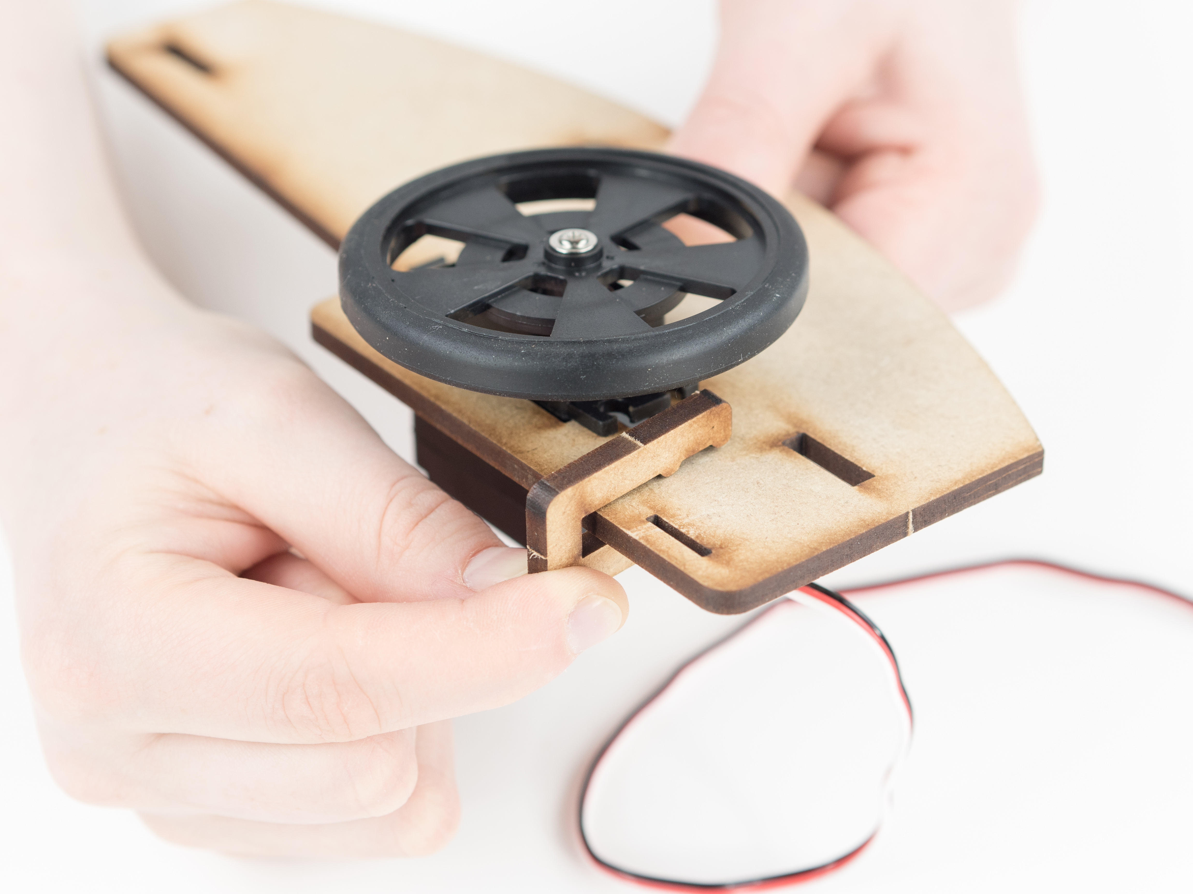
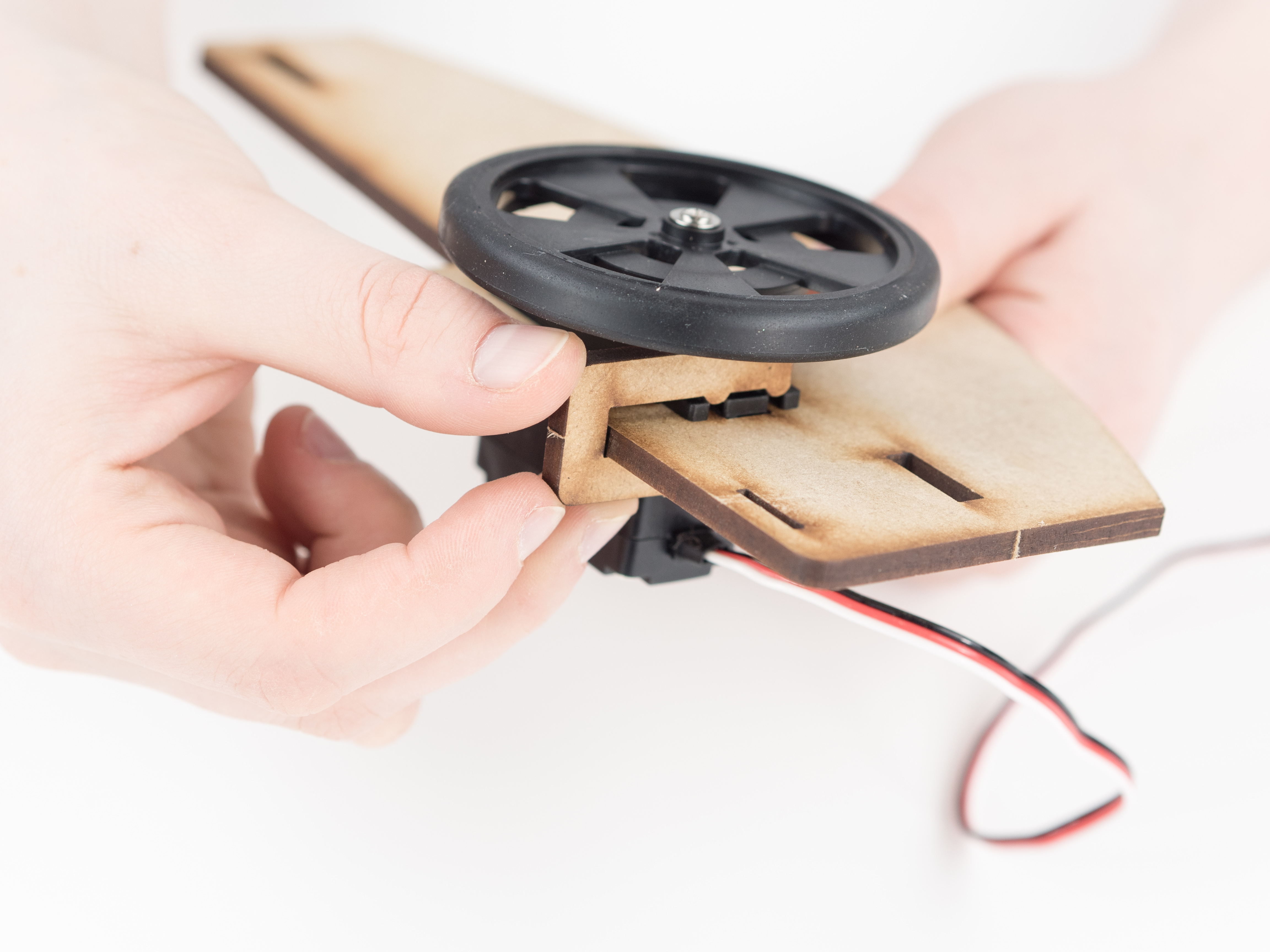
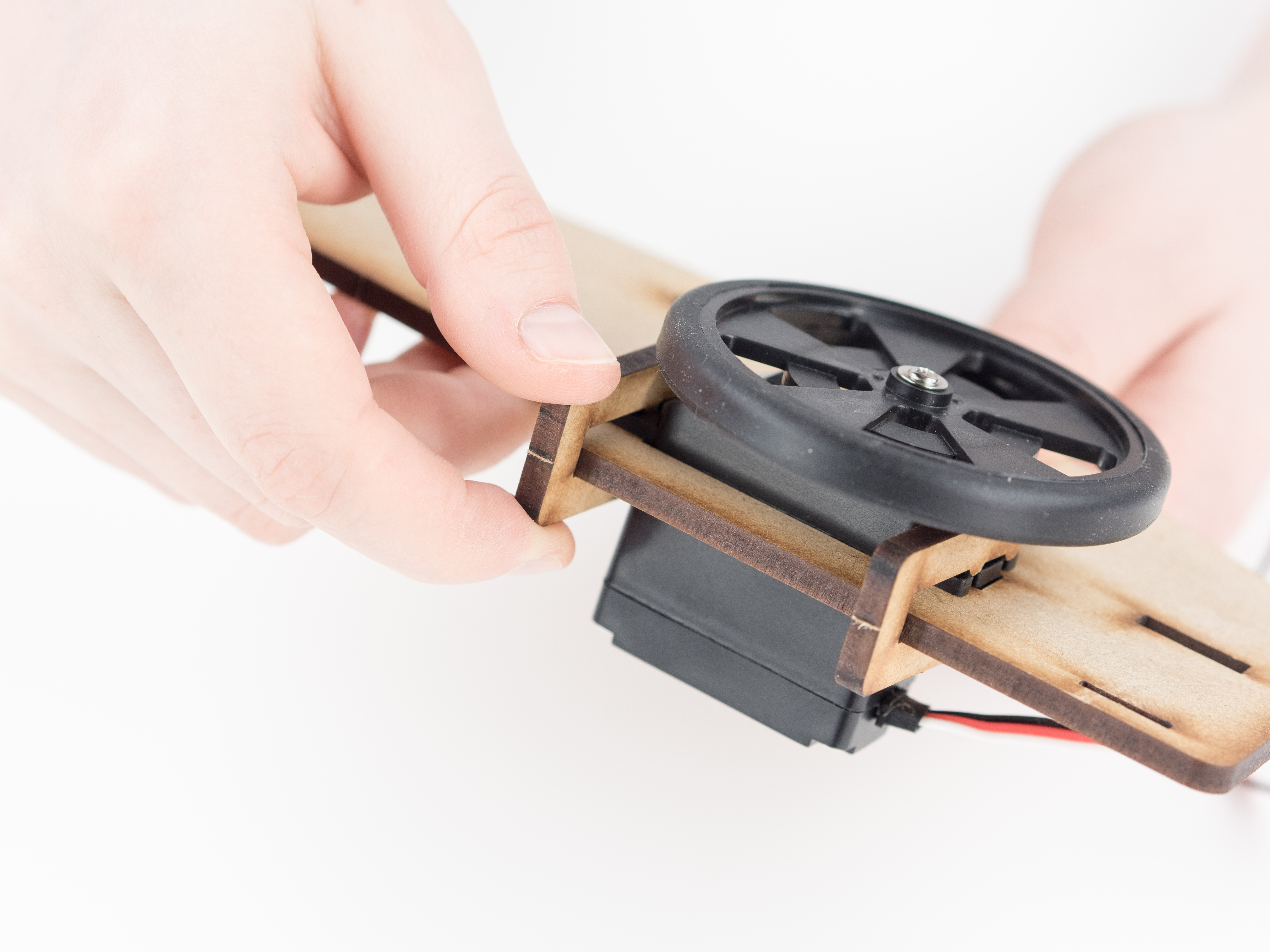
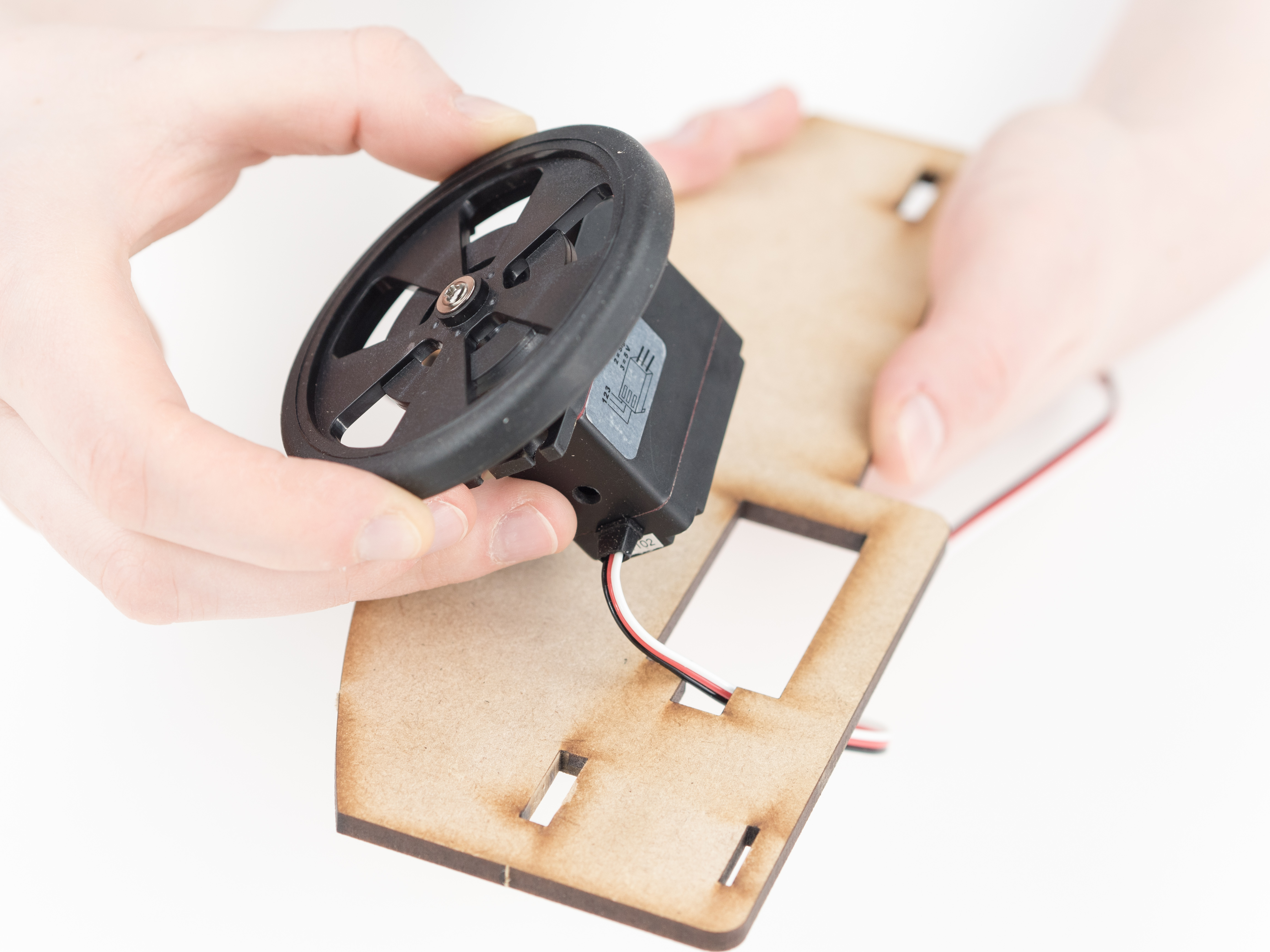
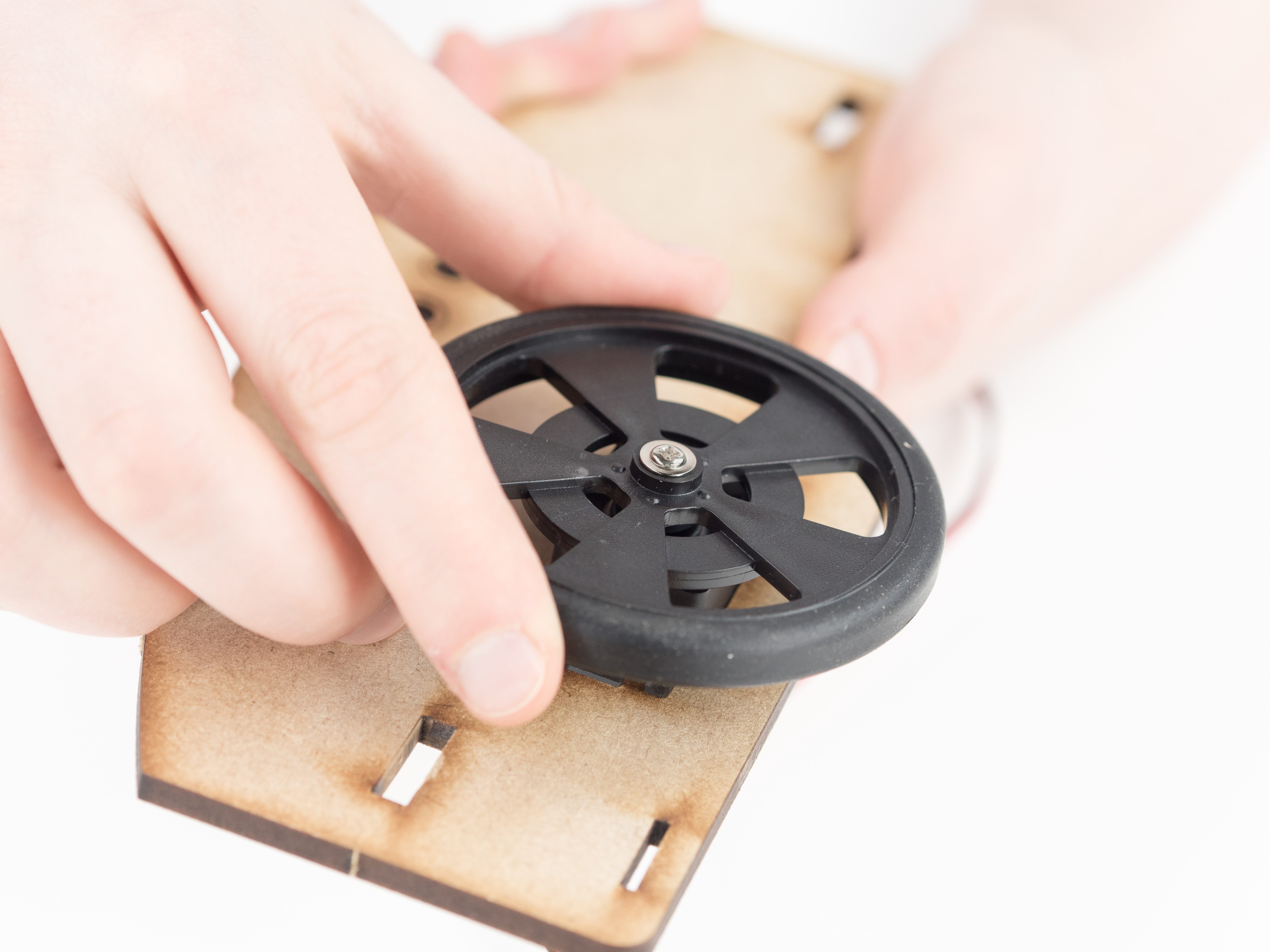
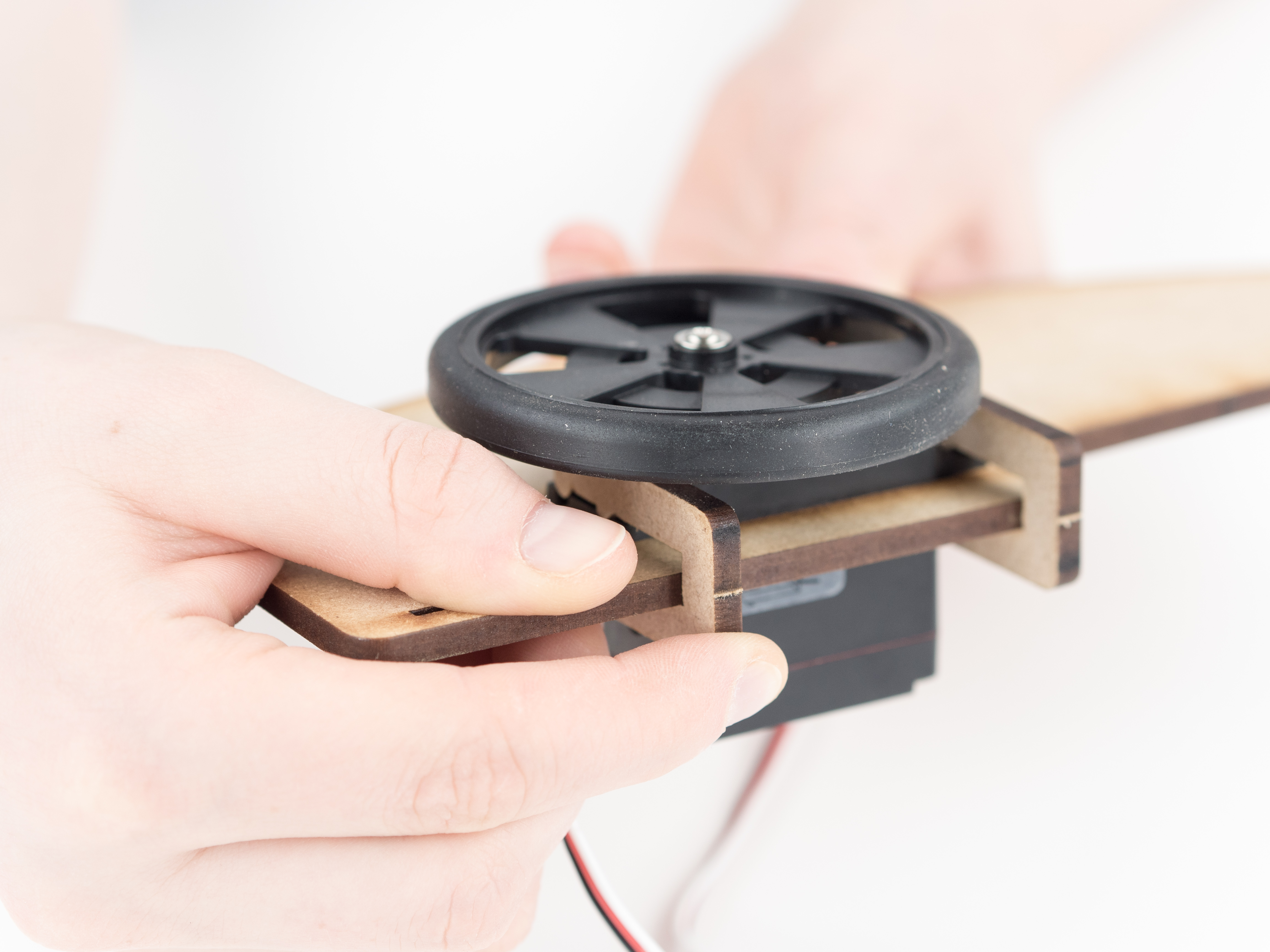
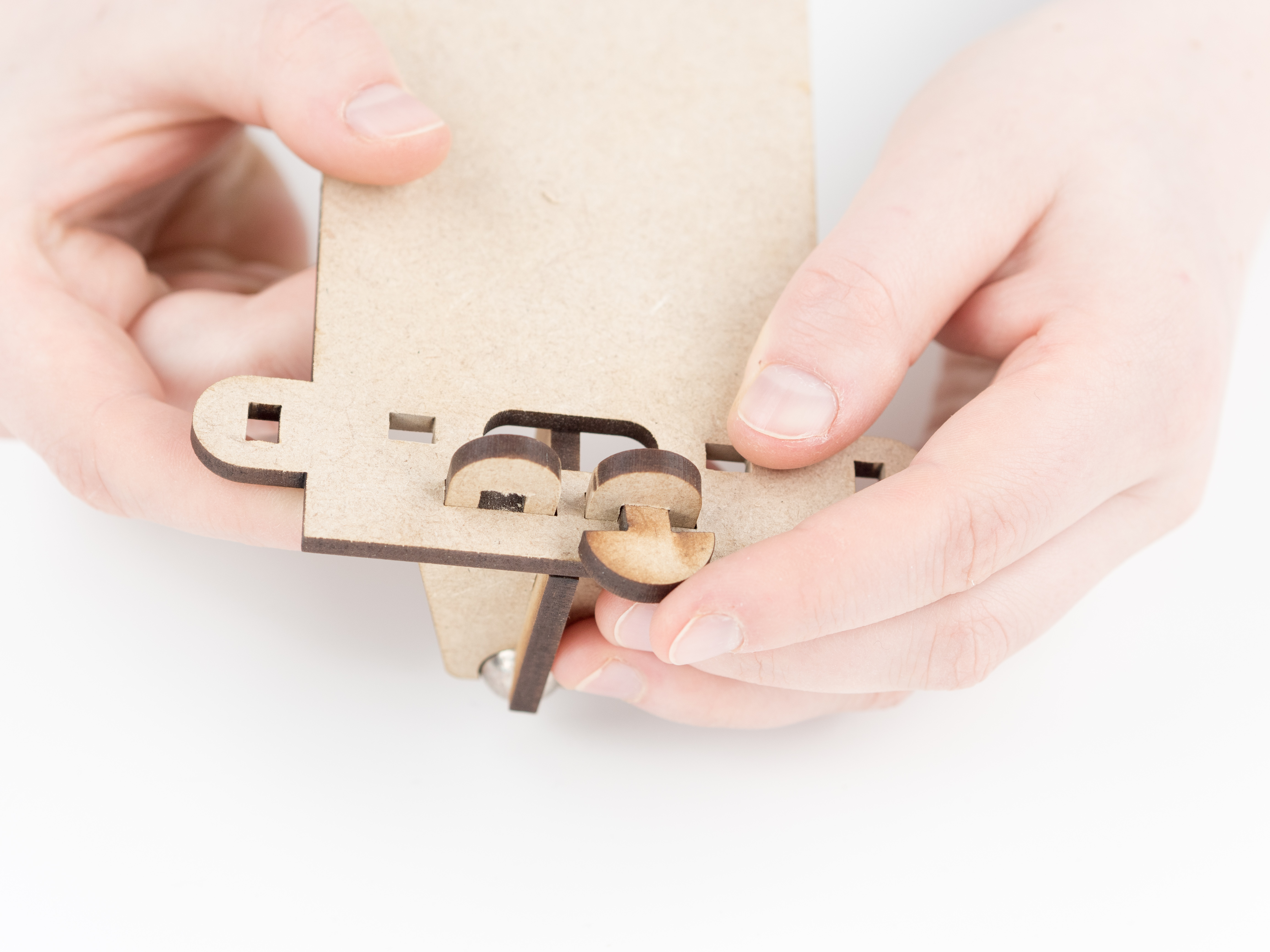
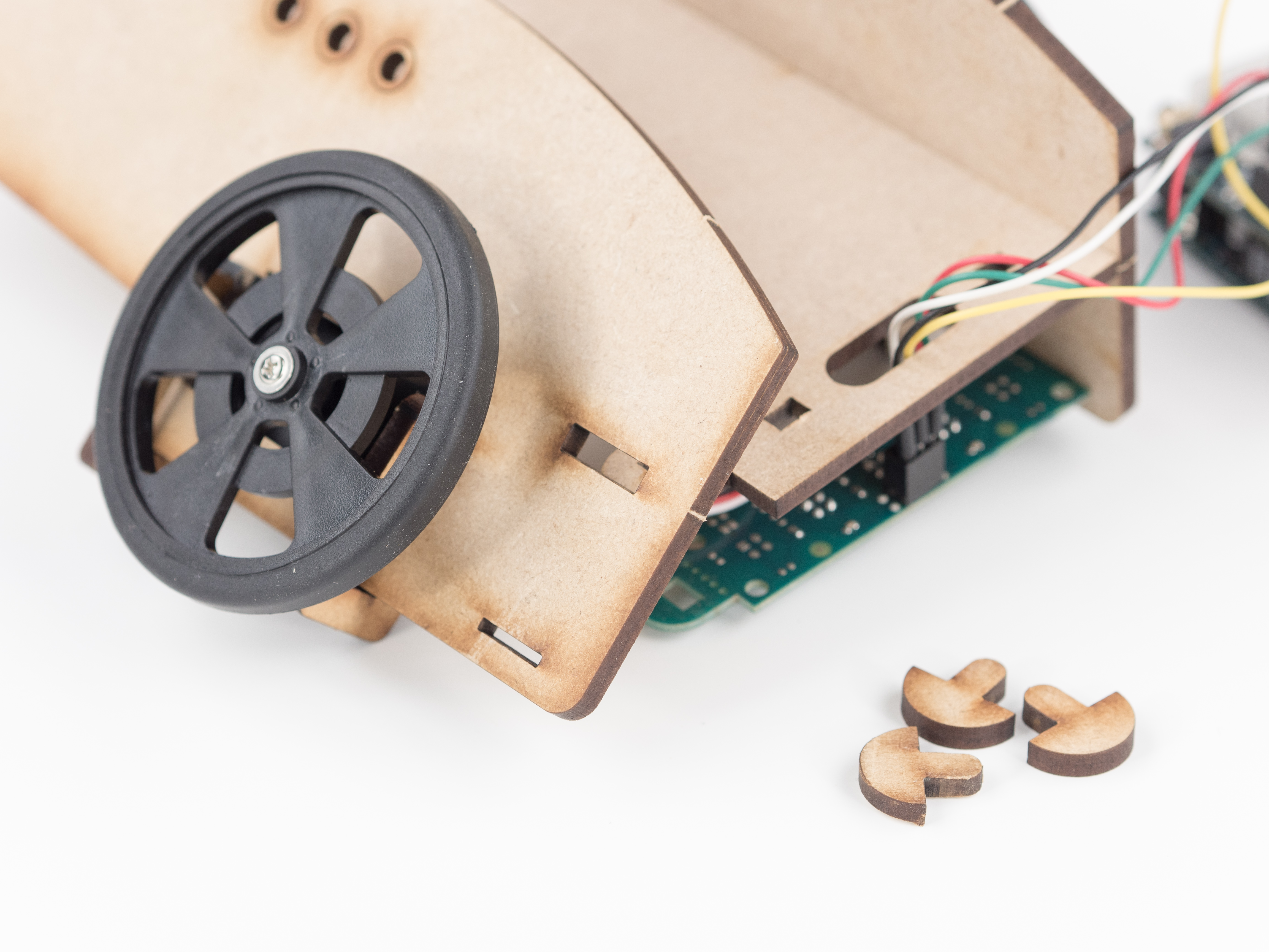
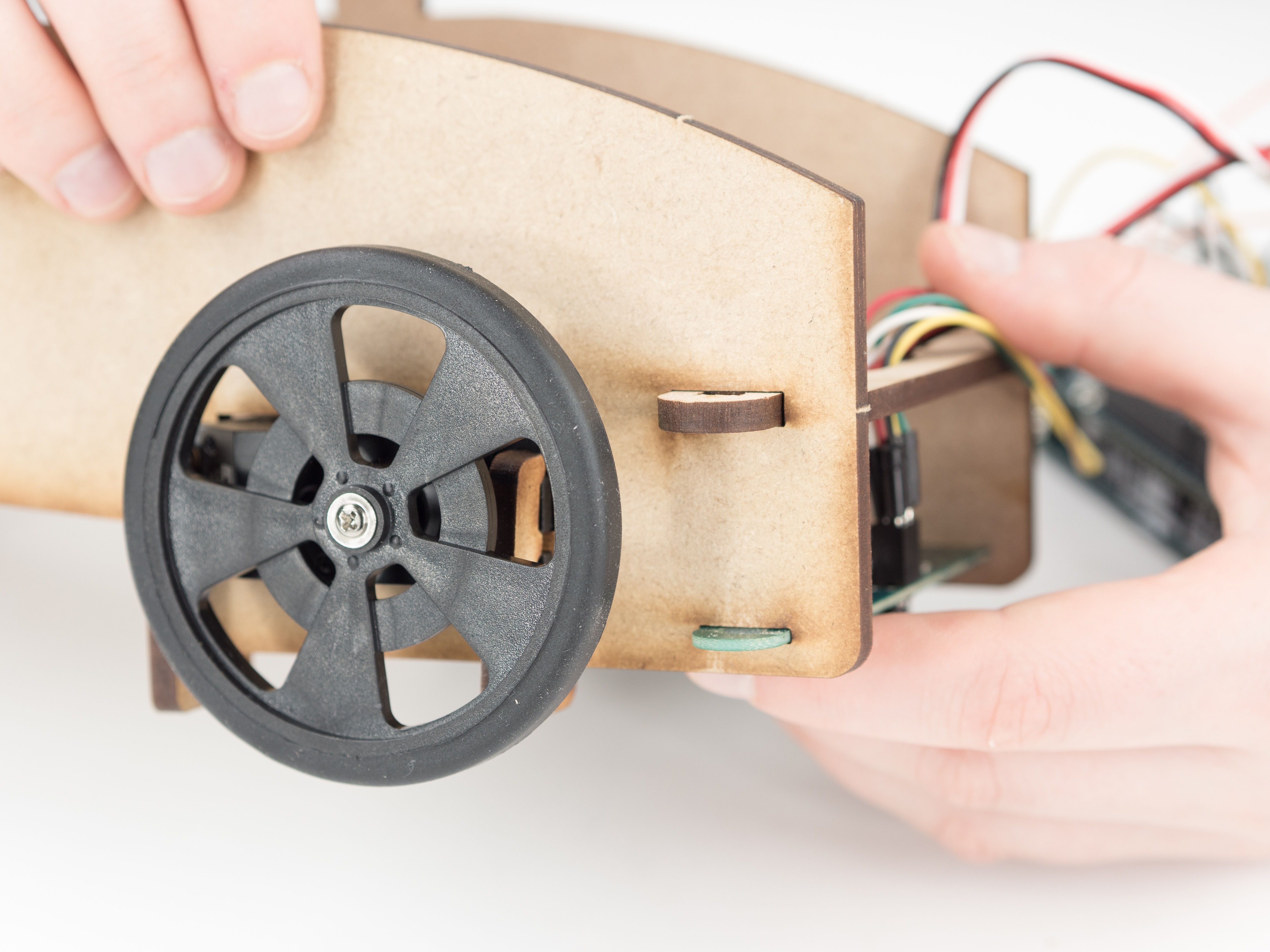
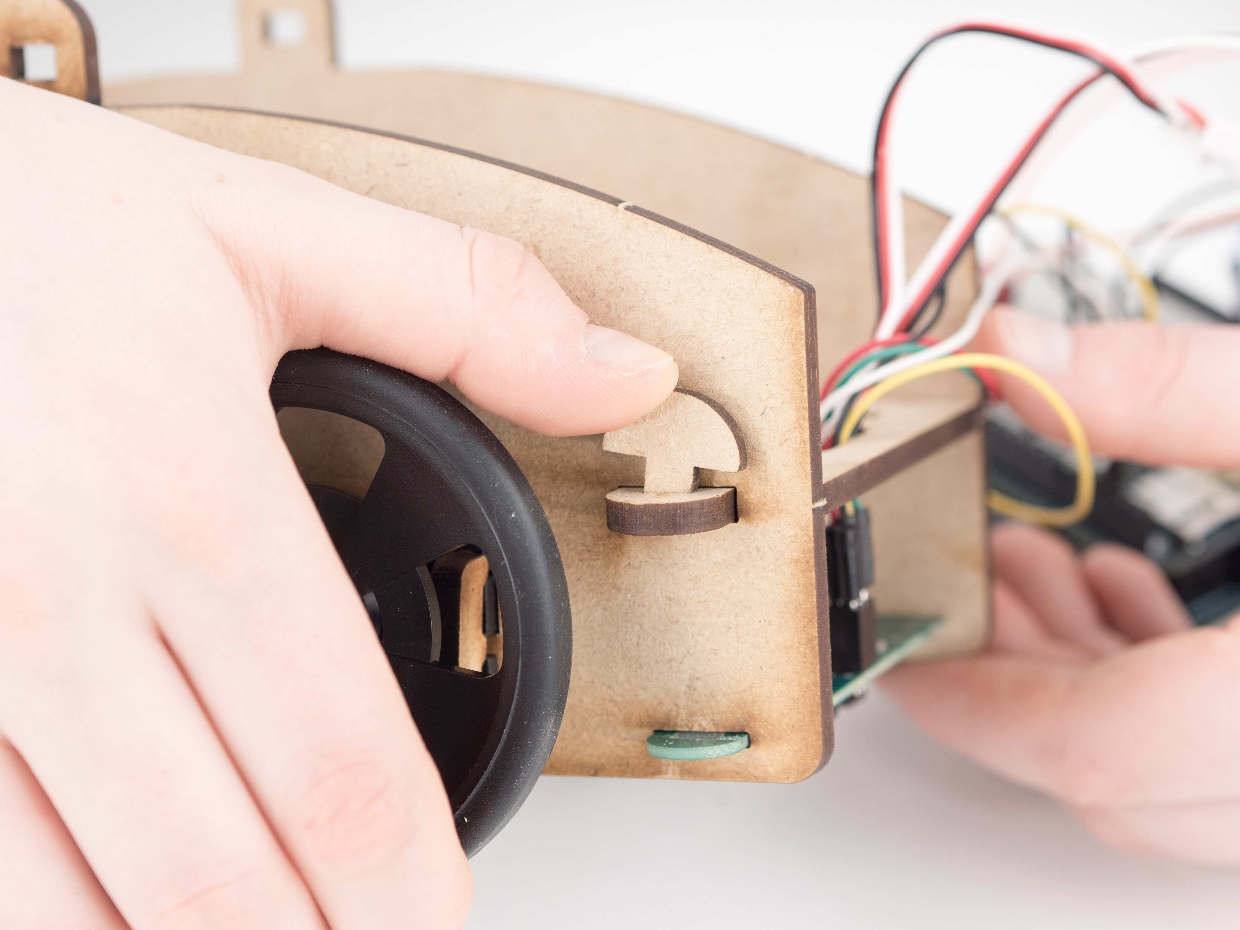
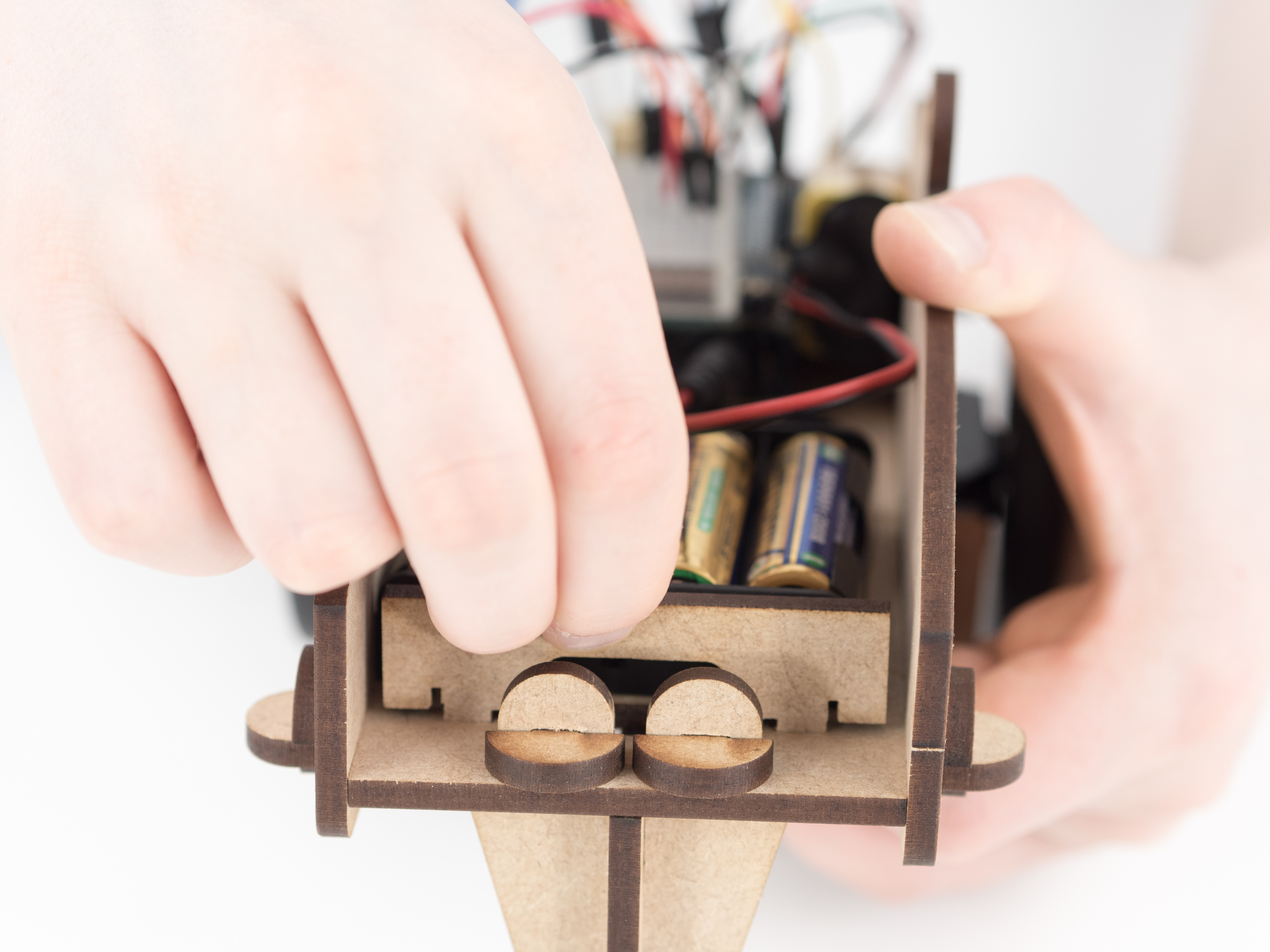
Make sure to screw the wheels to the continuous servos.
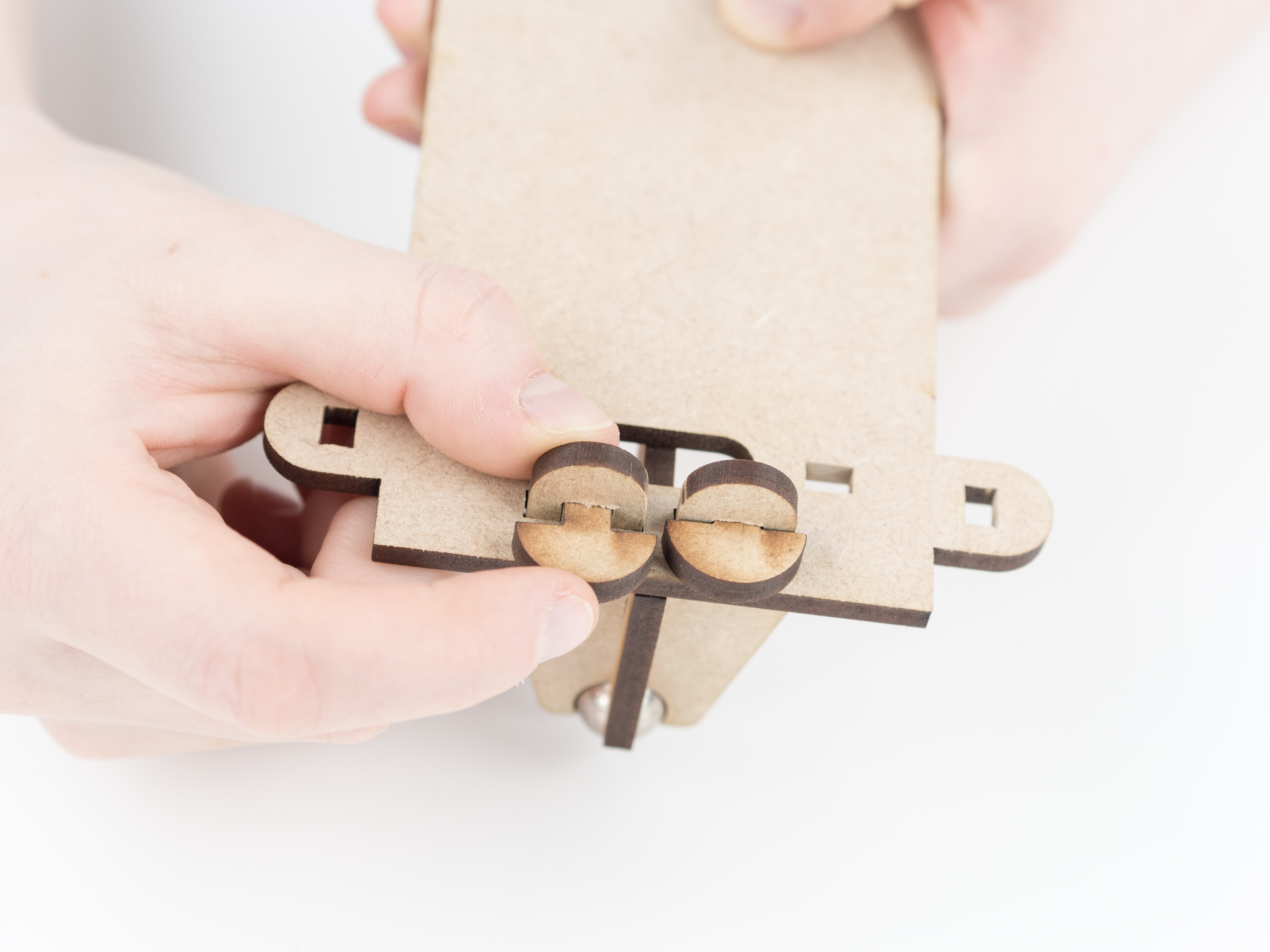
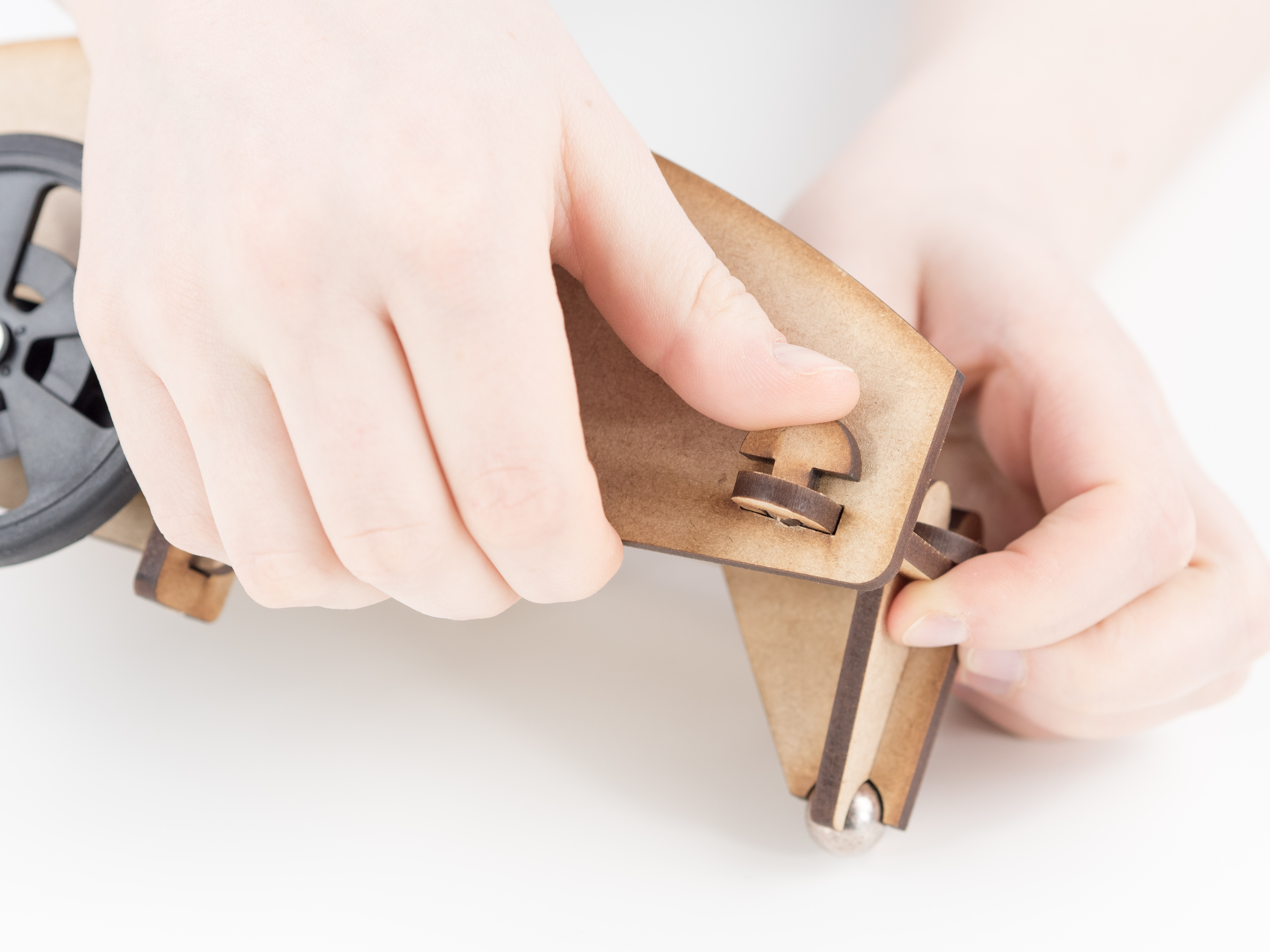
Step 6
Step 7
Step 8
Step 9
Step 10
Step 11
Step 12
Step 13
Step 14
Step 15
Step 16
Step 17
Step 18
Step 19
Step 20
Step 21
Step 22
Step 23
Step 24
Step 25
Step 26
Step 27
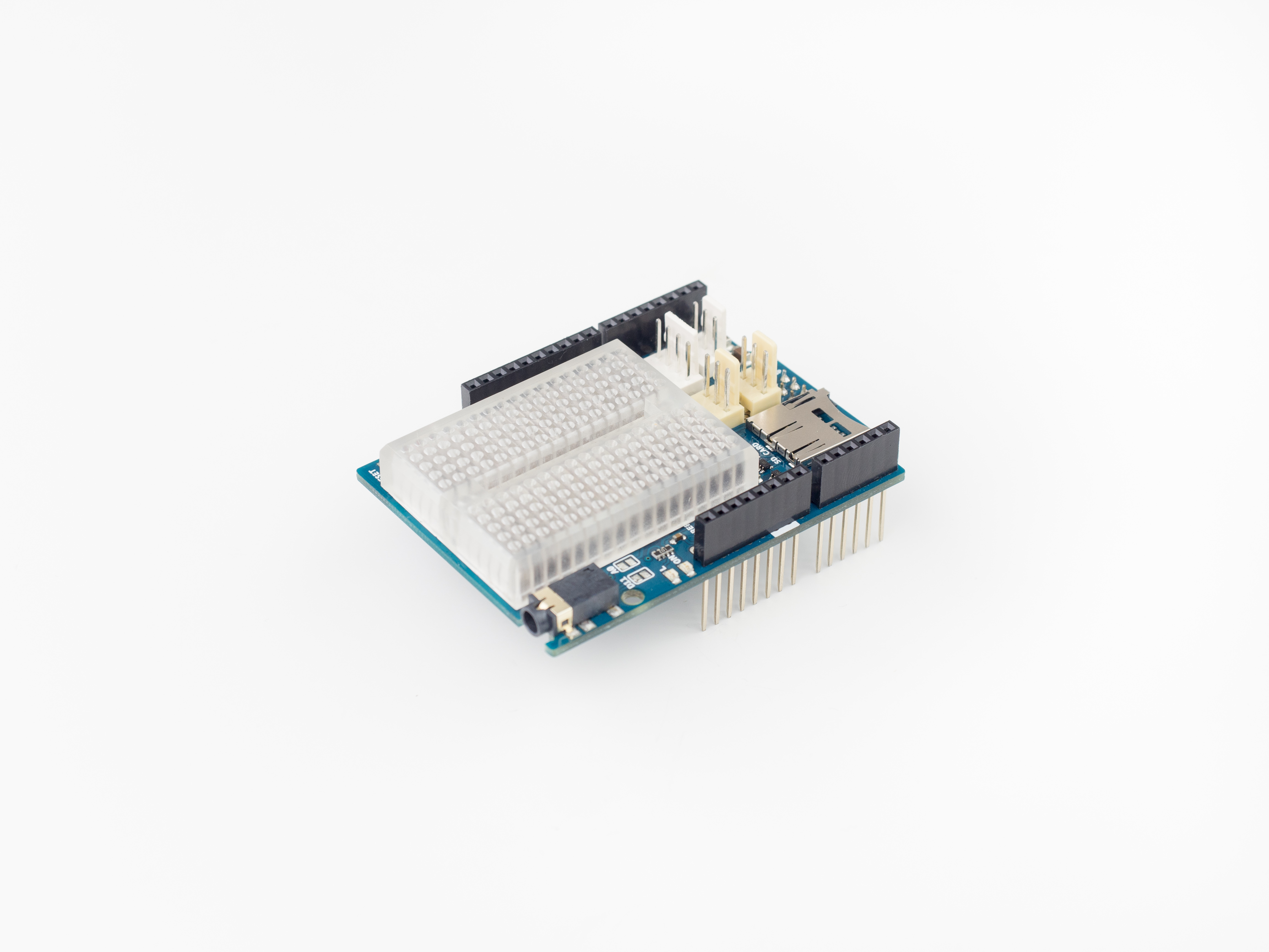
Attach the shield onto the top of the board.
Step 28
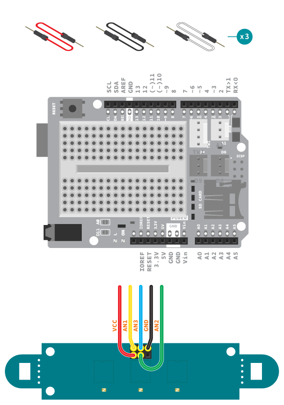
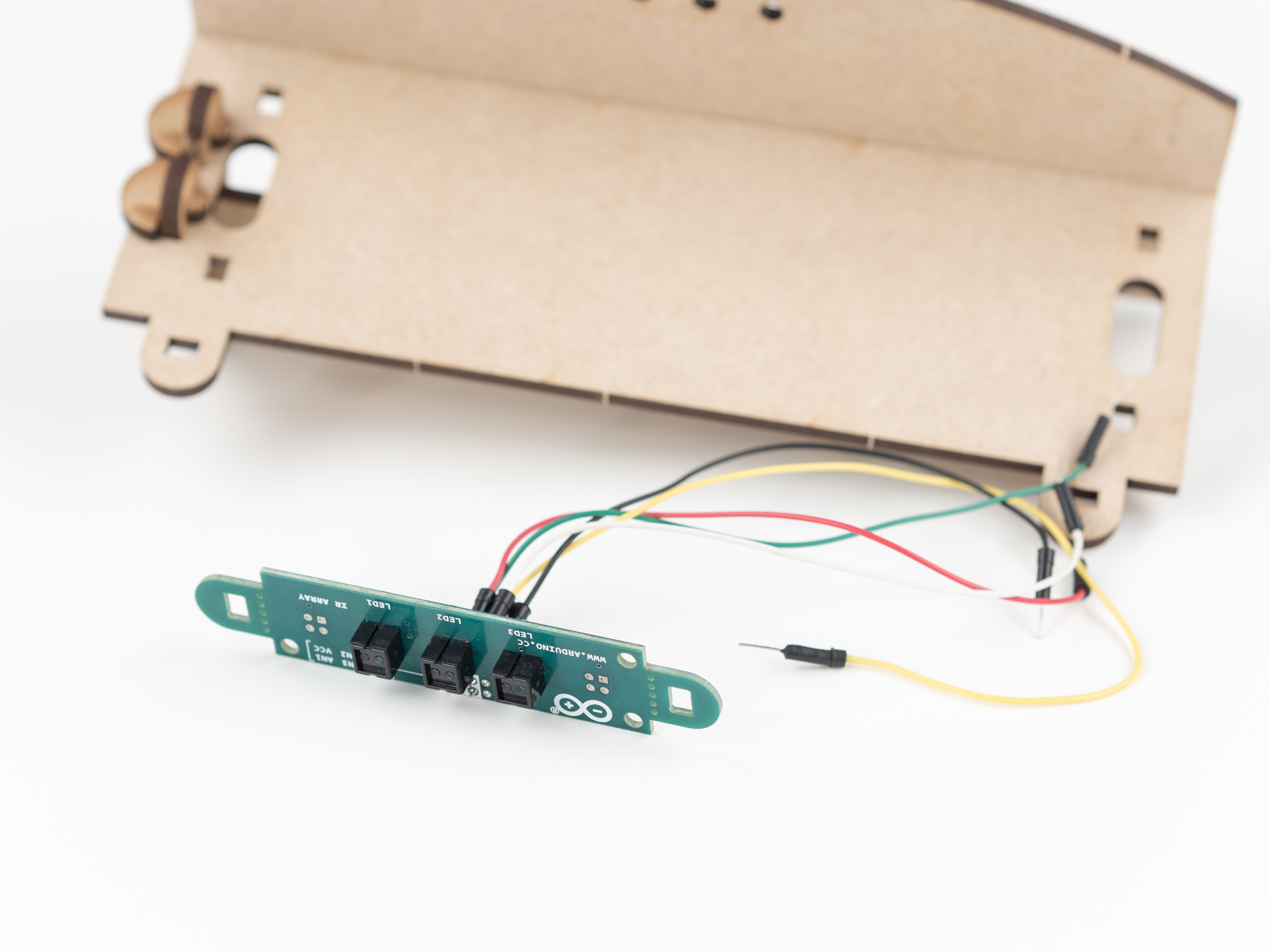
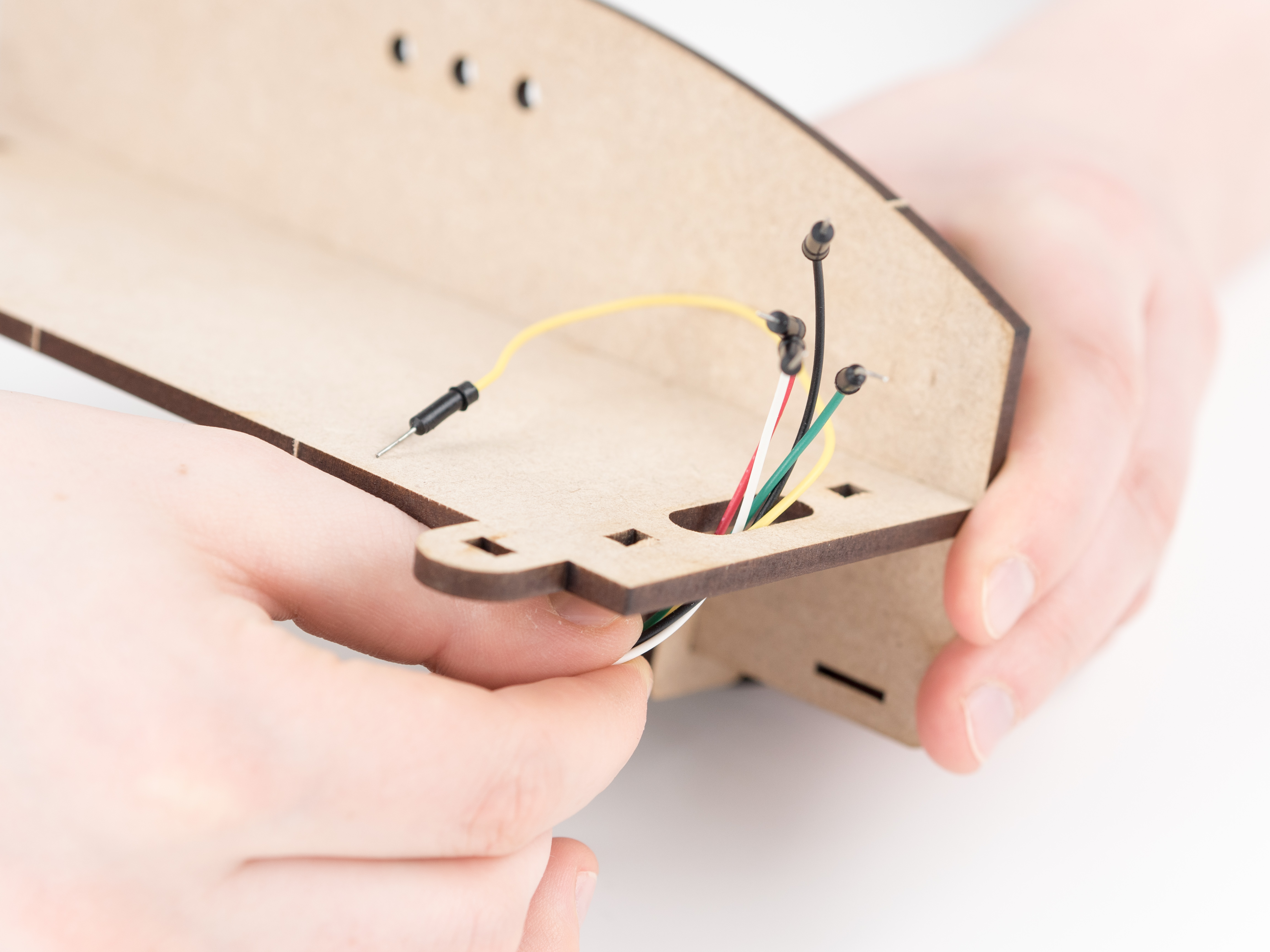
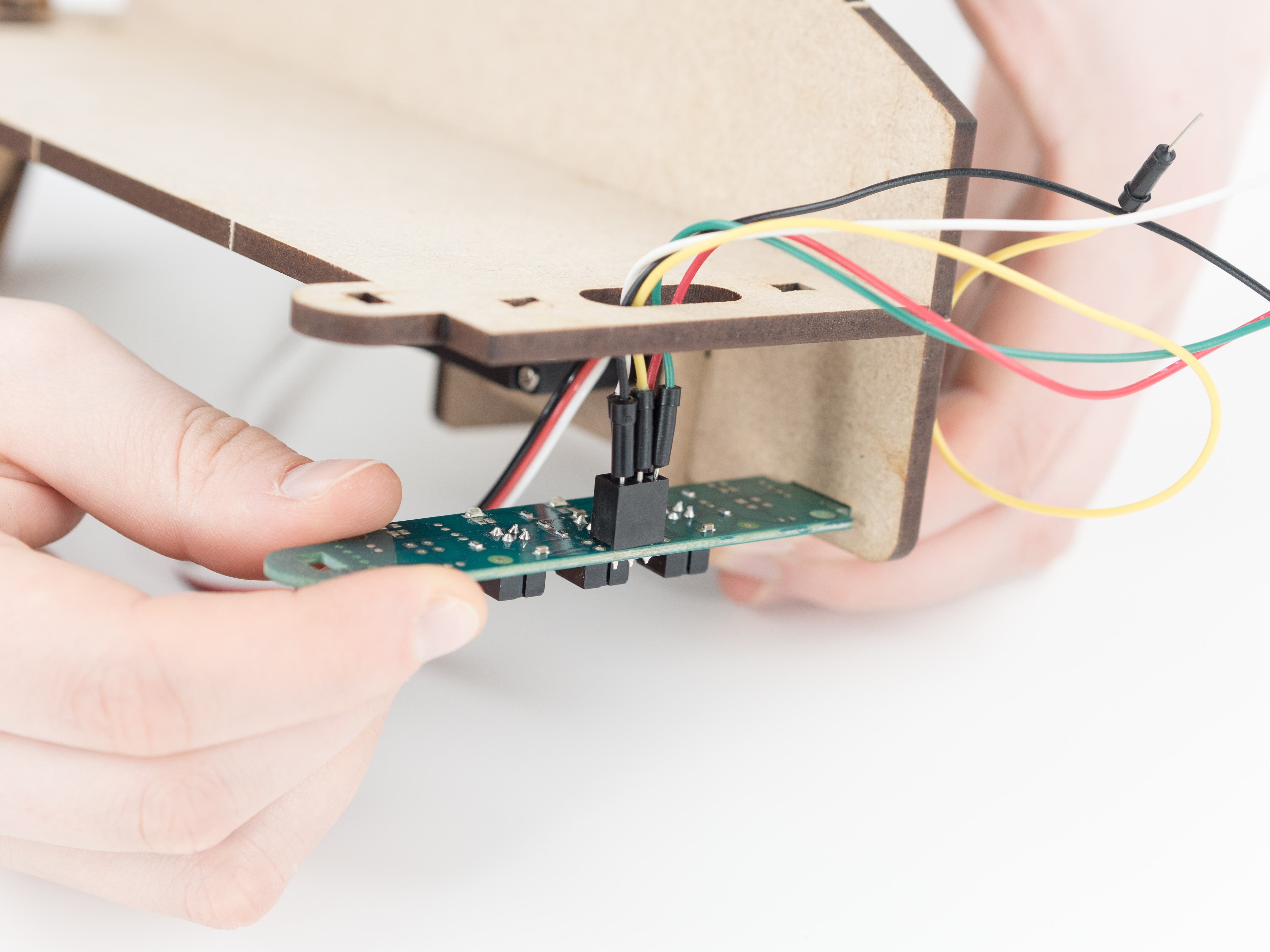
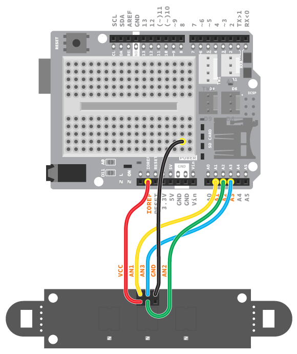
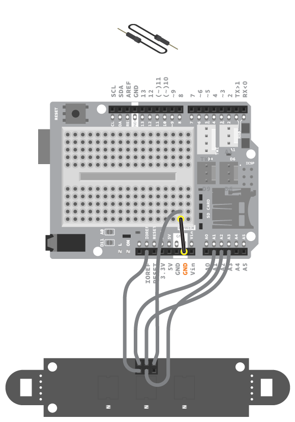
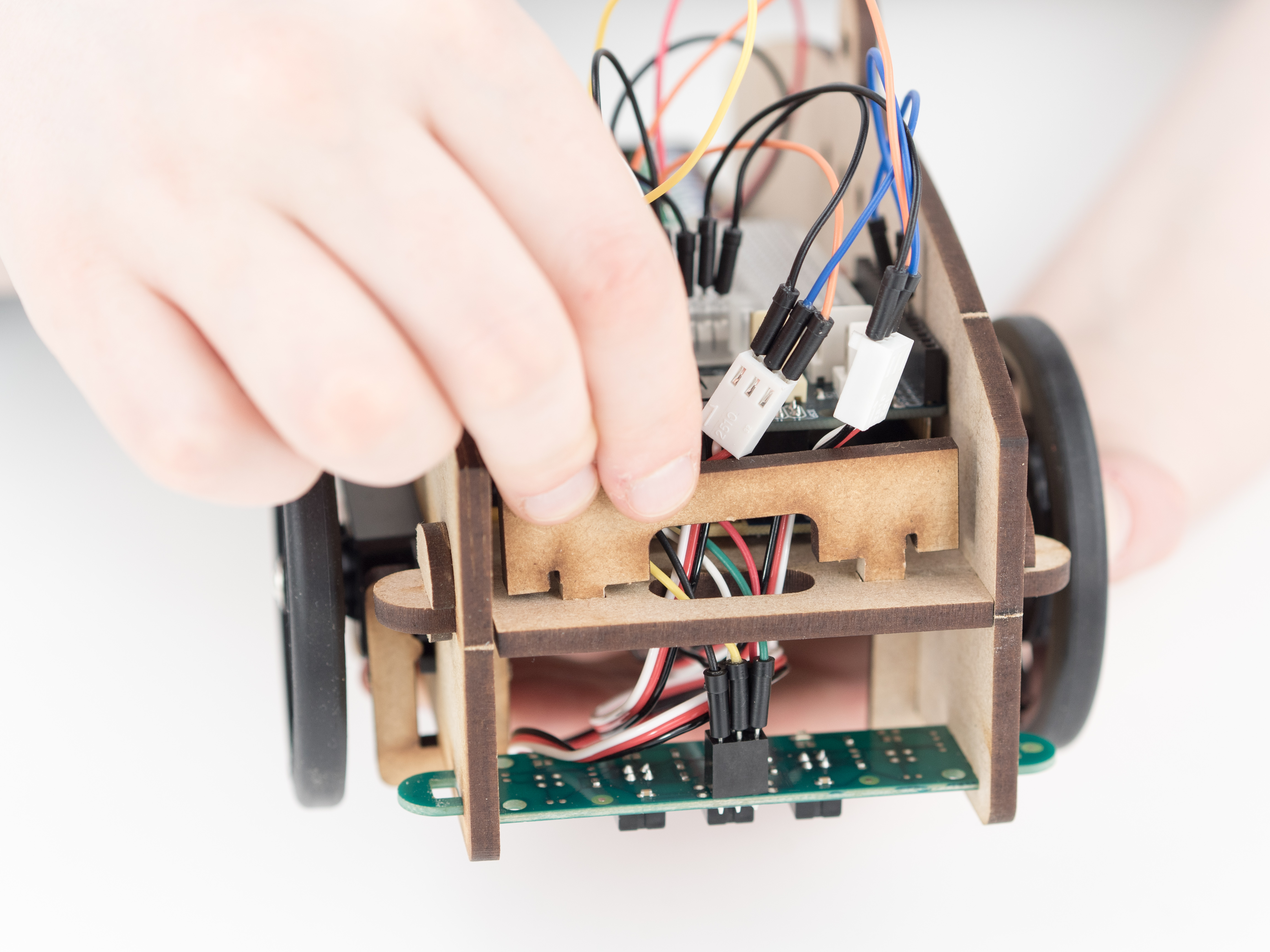
Connect 5 loose jumper wires to the IR Array, one to GND, another to VCC and three different colored ones to AN1, AN2 and AN3. These will later be connected to the board so remember what color is connected to what.
Step 29
Step 30
Step 31
Step 32
Step 33
Step 34
Step 35
Step 36
Step 37
Step 38
Connect the loose wires from the IR Array to the board . VCC to power, GND to the breadboard, AN1 to A1, AN2 to A2 and AN3 to A3.
Step 39
Connect GND to the same column in the breadboard as the GND from the IR Array.
Step 40
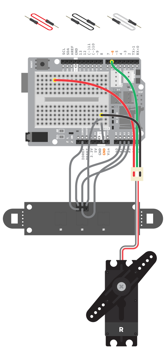
Using 3 jumper wires, connect the right servo. The black wire to GND, the white wire to digital pin 6, and the red wire to the breadboard.
Step 41
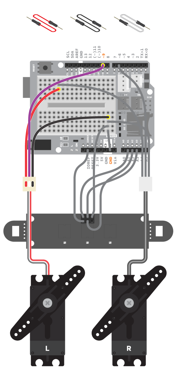
Using 3 jumper wires, connect the left servo. The black wire to GND, the white wire to digital pin 9, and the red wire to the breadboard.
Step 42
Step 43
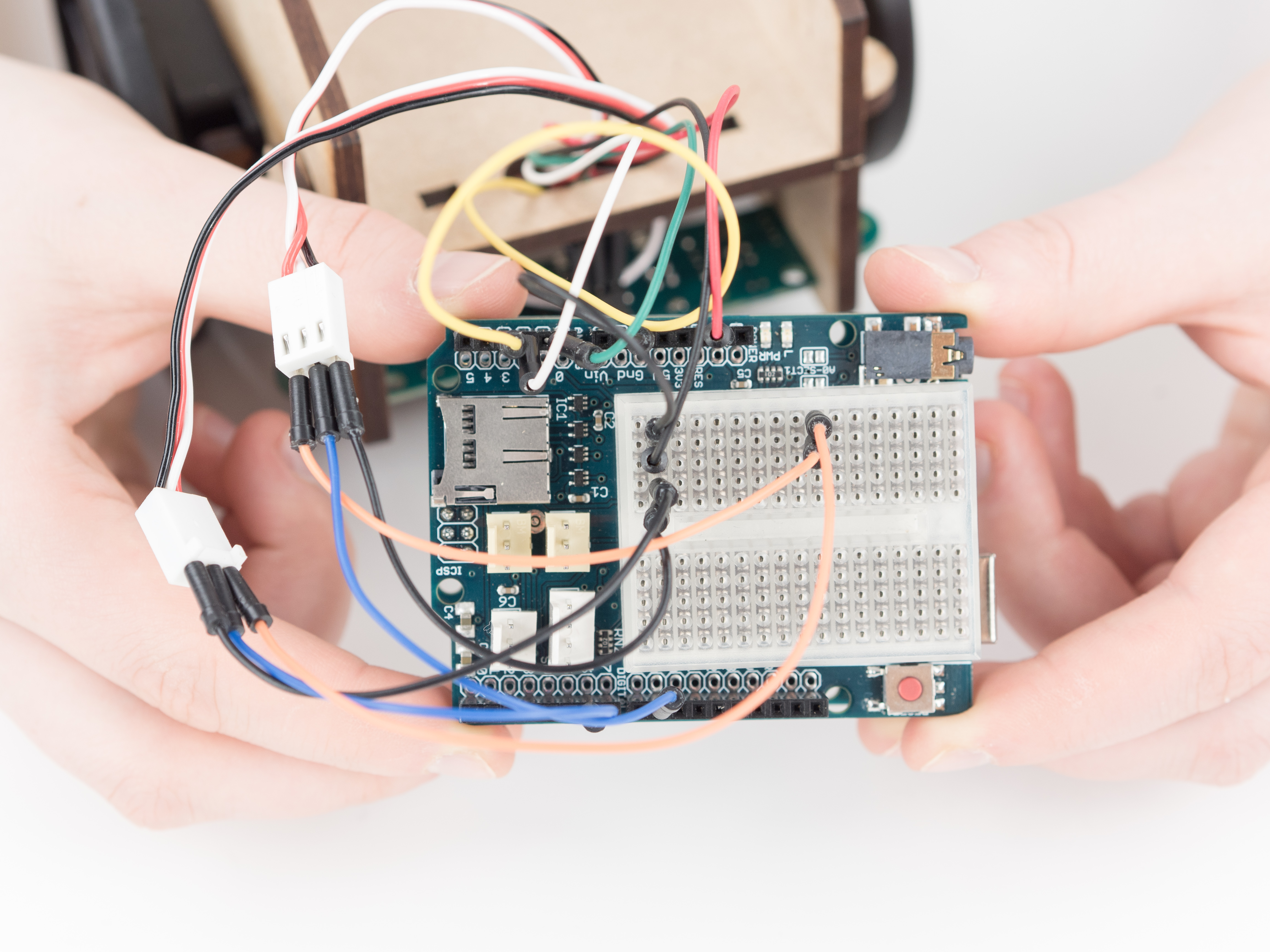
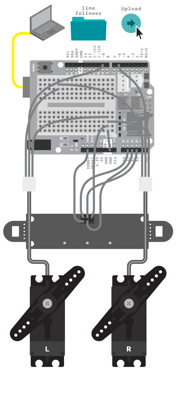
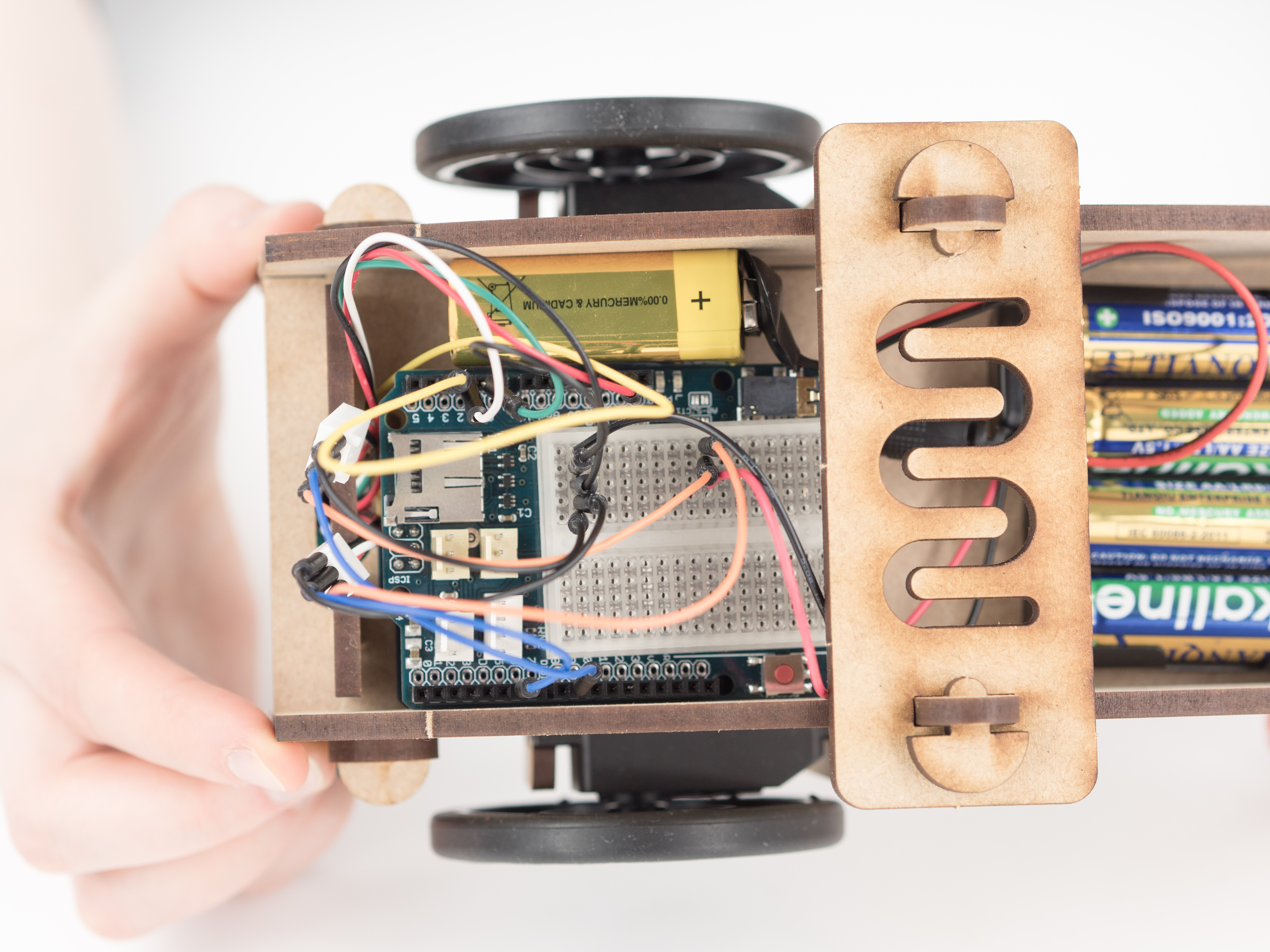
Check that your wiring is ready and connect the board to the computer.
Step 44
Copy the code:
/*
* LineFollower
* The Line Follower does exactly what the name suggests,
* it follows a line. Make it go where ever you want by
* showing the way with a 3 cm wide, black line.
*
* (c) 2013-2016 Arduino LLC.
*/#include<EducationShield.h>//IRArray(IR1, IR2, IR3)
IRArray ir = IRArray(A1, A2, A3);
//Wheels(left, right)
Wheels wheels=Wheels(6, 9);
voidsetup(){
wheels.begin();
//Use this line to set the threshold of the IR sensors. The default is 380. If you're using Arduino 101 board, use 530 instead.//Use test() to check the values of each sensor in loop()
ir.setThreshold(530);
delay(1000);
}
voidloop(){
int dir = ir.readLine();
wheels.follow(dir);
}
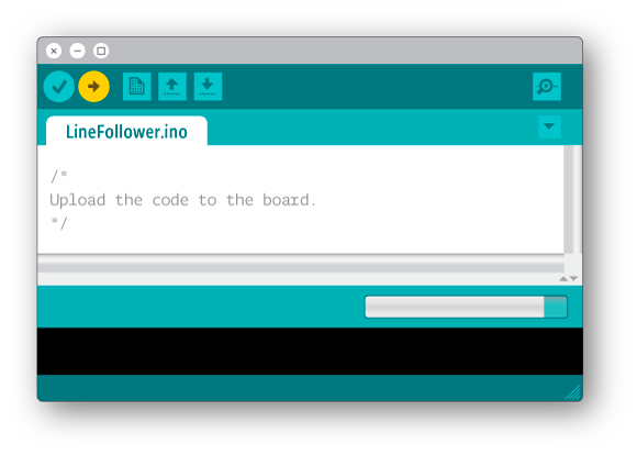
Step 45
Then upload the program to the board. Remove the USB cable, you will not run this project with it connected.
Step 46
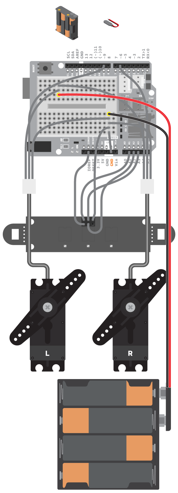
Prepare a 6 V battery with loose wires connector. Go to the Batteries reference if needed.
Step 47
Using the power plug with loose wires, connect the battery pack to the shield breadboard, black wire to GND and the red wire to the two servos’ power wires.
Step 48
Step 49
Step 50
Step 51
Step 52
Step 53
Step 54
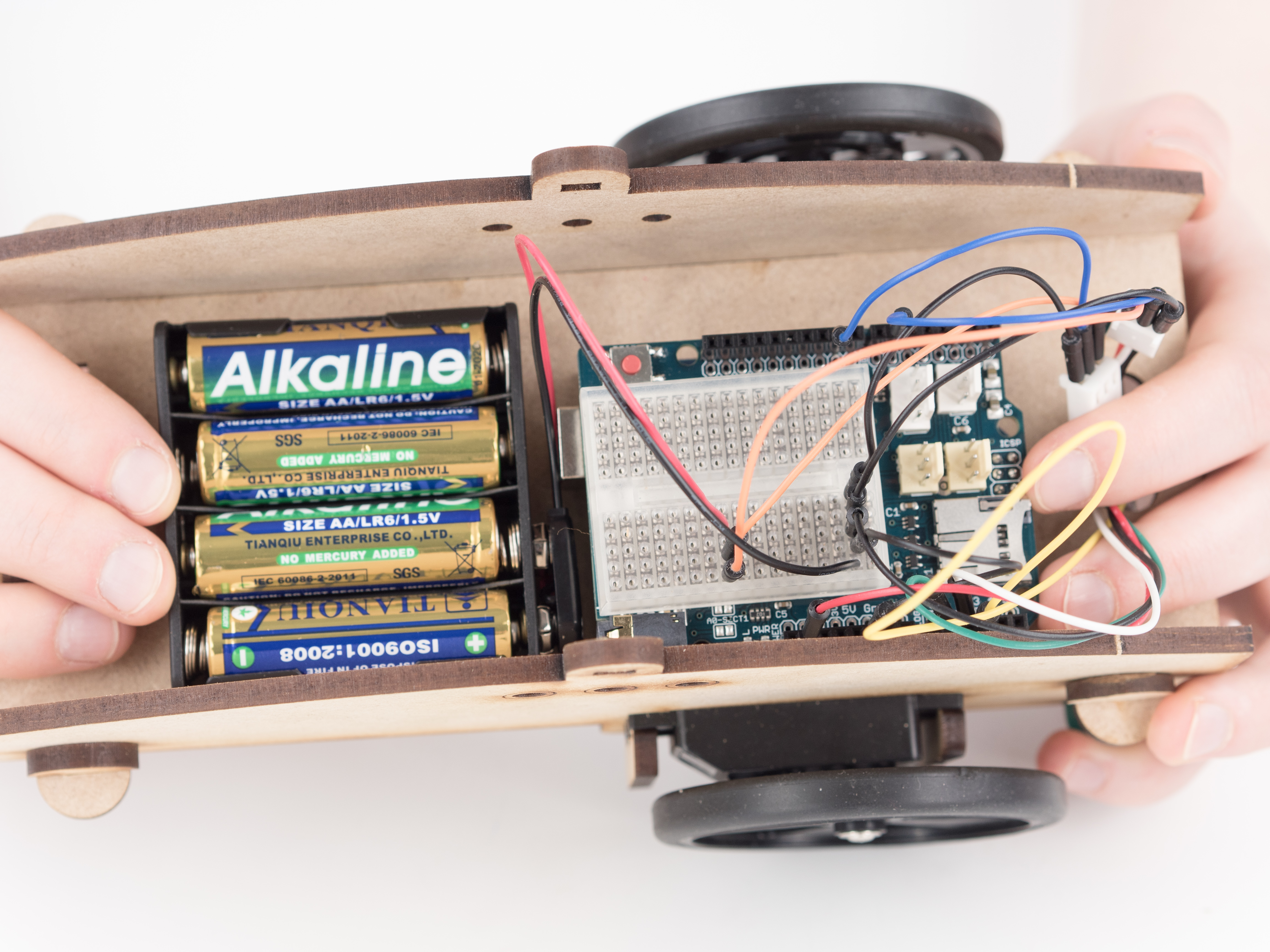
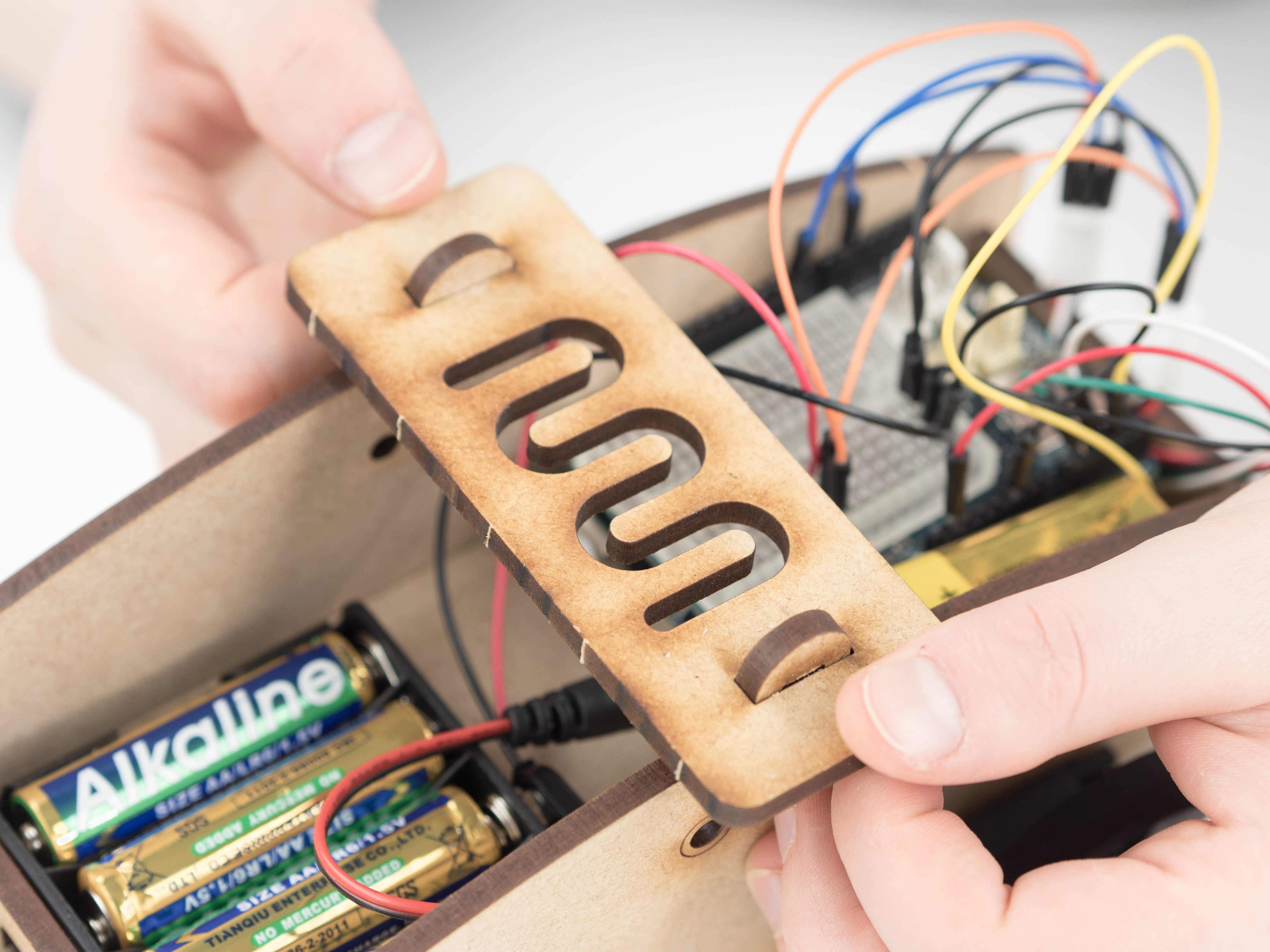
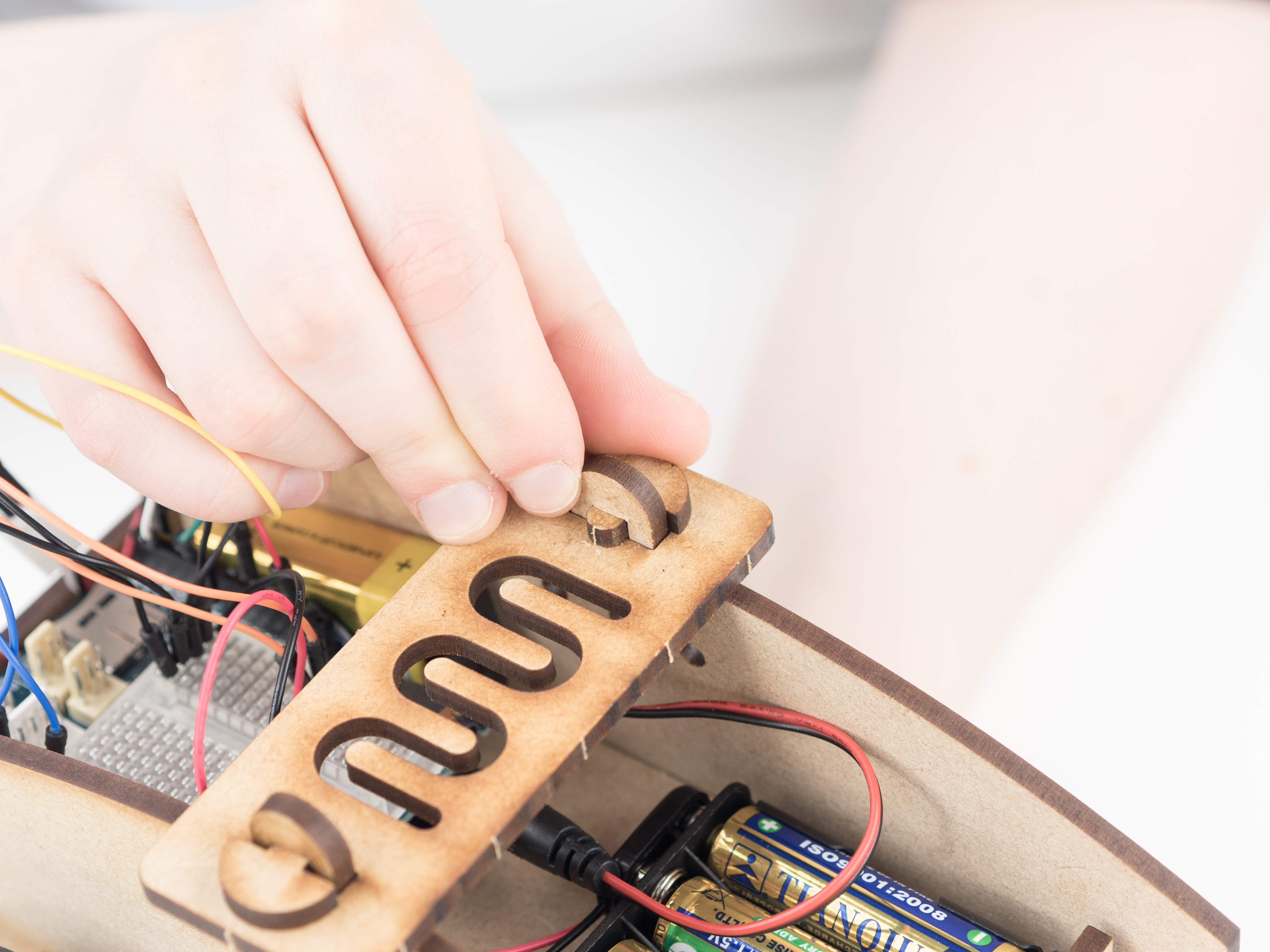
Prepare a 9 V battery with a power plug and put it inside the robot. Go to the Batteries reference if needed.
Step 55
Connect the 9 V battery to the board's power socket.
Step 56
Now create some 3 cm wide, black lines, and lets follow it!
Code
Find the code in File>Examples>EducationShield>Module4-Robots>Projects>LineFollower
http://verkstad.cc/urler/ctc-g-b4-p-4
How it works
The EducationShield library is included.
The IRArray and Wheel objects are declared, ir and wheel.
In setup() the wheels are initialized.
The threshold for the IRArray is set with ir.setThreshold(threshold). If you’re using the CTC 101 board the threshold is 530, if you’re using the CTC UNO board its 380.
The program pauses for 1000 milliseconds.
In loop(), the variable dir is declared to hold the value read from the IR array using readLine(). The value will be between -100 and 100 and represents
the direction the black line is heading.
wheels is set to follow the value of dir.
loop() continues to loop.
Note: Don't forget to change the threshold for the IRArray with ir.setThreshold(threshold) so that it fits with the board you’re using
Troubleshooting
Refer to the illustration and double check your connections. Make sure the shield and jumper wires are firmly connected.
If the motors are not working, see the reference wheels about how to debug servo motors used as wheels.
Print a track and build obstacles for the robot. If the obstacles are too difficult, see if there is a way to improve the robots performance by modifying the wheels.
Make the robot react in some way when it “sees” only white. That is, when it has lost the track of the black line.