To control the on board LED is pretty simple. The first example you will program is called Blink. To blink an LED means to repeatedly switch between the two possible states by turning it on and off. Like the way processing programs always need to have a setup() and a draw() function, we now need to have a setup() and a loop():
- setup(): This part of the program runs only once at the beginning. This is where you tell the board what pins you are going to use, and if you are going to use them as inputs or outputs.
- loop(): This part will run forever (or until you disconnect the power source). The commands in loop() are executed in order, one after another. When reaching the last line, it will start from the beginning again.
Example 2.1
In this example, you will make the on-board LED blink.
Materials
- 1 x control board
Instructions
- Open the IDE and write the following code:
- Connect the control board to your computer using the USB cable.
- Compile and upload the code to the board using this icon in the IDE.

http://verkstad.cc/urler/ctc-g-b2-c-1
Result
The on-board LED should now blink with a 2 second interval, being turned on for 1 second and then turned off for 1 second.
Commands
- pinMode (pin Number, INPUT | OUTPUT | INPUT_PULLUP): Used to determine what the digital pin is doing on the board, (OUTPUT) for output (INPUT | INPUT_PULLUP) for signals going into the board.
- digitalWrite(pinNumber, HIGH/LOW): writes HIGH or LOW to the digital pin pinNumber.
- delay( time ): Stop the program for a certain amount of time. The time is expressed in milliseconds. If you want to stop the program for 2 seconds, you should write delay (2000).
Remember:
- Every line ends with a semicolon ;.
- Blocks of code are contained within curly brackets { }.
- Functions start with a definition like void.
- Functions have parameters contained between brackets ( ). The amount of parameters depend on the function.
How it works
- In setup(), pin 13 is configured as an output. This is the digital pin which the on-board LED is connected to.
- In loop(), the on-board LED is turned on by writing HIGH to pin 13. This means that you send 5V to digital pin 13.
- The program pauses for 1000 milliseconds, or 1 second.
- The on-board LED is turned off by writing LOW to pin 13. This means that you send a "1" to digital pin 13.
- The program pauses for another 1000 milliseconds.
- loop() continues to loop.
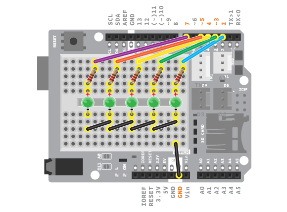
Add Your Own LEDs
You can add your own LEDs to the circuit. Any electronic circuit you connect needs to be connected to power and ground for the electricity to flow through and power your components. On the control board, power is provided through the IOREF power pin or one of the digital pins (when set to HIGH). The ground pins are marked as GND.
When working with an LED you need to remember that they have polarity. LEDs are constructed to show this. The long leg, named anode, is positive. When wiring it in a circuit, this leg should be connected to power, in this case a digital pin because you want to be able to control it. The short leg, or cathode, is negative and should be connected to GND.
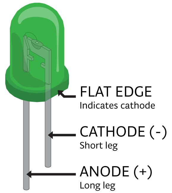
LEDs will not break if you connect them in the opposite way, but they will not work. LEDs cannot carry a lot of current through them. In order to protect them from burning, you need to put a resistor in serial with them. The value of that resistor varies, in the CTC examples a 220 Ohm resistor is always used with an LED. Read more about resistors and Ohm's law here.
To make circuits easier, you will use the Education shield. When mounted on your control board the shield extends the boards capabilities as well as it brings a few extra features. To make a circuit with an LED you will need to use the breadboard on top of the shield. Read more about the breadboard here, and about the Education shield here.
Example 2.2
In this example, you will connect an LED to your control board and make it blink.
Materials
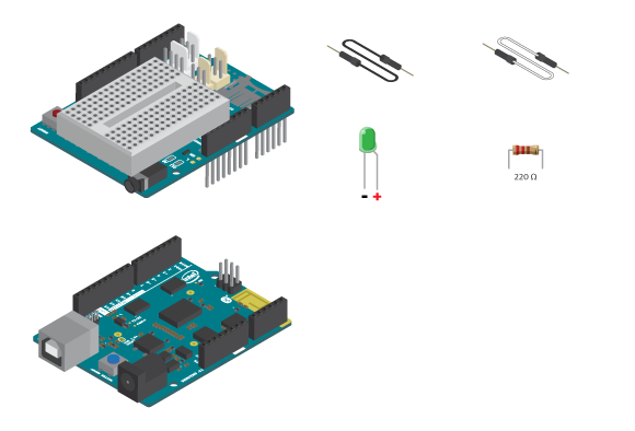
- 1 x control board
- 1 x Education Shield
- 1 x LED
- 1 x 220 ohm resistor
- 2 x jumper wire
Instructions
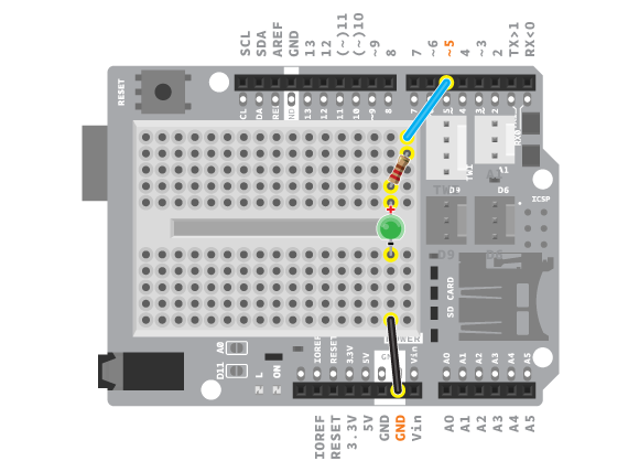
- Attach the shield onto the top of the control board.
- Connect the LED across the breadboard gap.
- Connect a 220 ohm resistor to digital pin 5 using a jumper wire. Connect the resistor to the long leg of the LED.
- Connect the short leg of the LED to GND using a jumper wire.
- Write the code.
- Upload the code:
http://verkstad.cc/urler/ctc-g-b2-c-2
Result
As in the previous example, the LED should blink with a 2 second interval.
How it works
- In setup(), pin 5 is configured as an output. This is the digital pin which the LED is connected to.
- In loop(), the LED is turned on by writing HIGH to pin 5.
- The program pauses for 1000 milliseconds.
- The LED is turned off by writing LOW to pin 5.
- The program pauses for another 1000 milliseconds.
- loop() continues to loop.
Example 2.3
In this example, you will modify example 2.2 slightly. You will keep the same circuit but use a variable to hold the digital pin number where the LED is connected, instead of just writing the number. Check the variable section in the previous Module, if you need help remembering what a variable is.
Instructions
- Write the following into the IDE
- Compile and upload the program:
http://verkstad.cc/urler/ctc-g-b2-c-3
Result
This example should do exactly the same as the previous one.
How it works
- The variable ledPin is declared to hold the value 5, the number of the digital pin you are using.
- In setup(), pin 5 is configured as an output, using the variable ledPin.
- In loop(), the LED is turned on by writing HIGH to pin 5, using the variable ledPin.
- The program pauses for 1000 milliseconds.
- The LED is turned off by writing LOW to pin 5.
- The program pauses for another 1000 milliseconds.
- loop() continues to loop.
Learn by doing
- Try and see what happens when you change the times inside the delay function. Try making the delays smaller, to see what will happen. Test different ways to make the light blink faster or slower.
- Use the light to simulate a heartbeat. Check your heartbeat by measuring your pulse. You will notice that you always get two pulses, something like tick tock … pause … tick tock … pause … Try to simulate that with an LED. (HINT: you can copy and paste code)
- Finally, test to see what happens when the delay becomes really small. Try and notice if you can still see the light blink when you change to delay(10).
VU-meter
It is possible to connect and control more than one LED with your Arduino. When you are using several LEDs in a line, this is called a VU-meter in the CTC program. The EducationShield library contains a class called vuMeter with several functions you can use to easily control several LEDs. Read more about the VU-meter here.